Pressure Sensors
Pressure switches are not the only pressure sensing de- vices that an electrician is likely to encounter on the job, especially in an industrial environment. It is often necessary to know not only if the pressure has reached a certain level, but also to know the amount of pressure. Although sensors of this type are generally considered to be in the
instrumentation field, an electrician should be familiar
with some of the various types and how they operate.
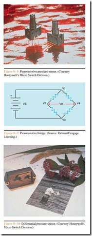
Pressure sensors are designed to produce an output voltage or current that is dependent on the amount of pressure being sensed. Piezoresistive sensors are very popular because of their small size, reliability, and accuracy (Figure 8 – 8). These sensors are available in ranges from 0 to 1 psi and 0 to 30 psi. The sensing element is a silicon diaphragm integrated with an inte- grated circuit chip. The chip contains four implanted piezoresistors connected to form a bridge circuit (Fig- ure 8 – 9). When pressure is applied to the diaphragm, the resistance of piezoresistors changes proportionally Another type of piezoresistive sensor is shown in Figure 8 – 10. This particular sensor can be used to sense absolute, gage, or differential pressure. Units are available that can be used to sense vacuum. Sensors of this type can be obtained to sense pressure ranges of 0 to 1, 0 to 2, 0 to 5, 0 to 15, 0 to 30, and 0 to -15 (vac- uum). The sensor contains an internal operational am- plifier and can provide an output voltage proportional to the pressure. Typical supply voltage for this unit is 8 volts DC. The regulated voltage output for this unit is 1 to 6 volts. Assume for example that the sensor is in- tended to sense a pressure range of 0 to 5 psi. At 0 psi,
Sensors can also be obtained that have a ratio- metric output. The term ratiometric means that the output voltage will be proportional to the supply volt- age. Assume that the supply voltage increases by 50% to 12 volts DC. The output voltage would increase by 50% also. The sensor would now produce a voltage of 1.5 volts at 0 psi and 9 volts at 15 psi.
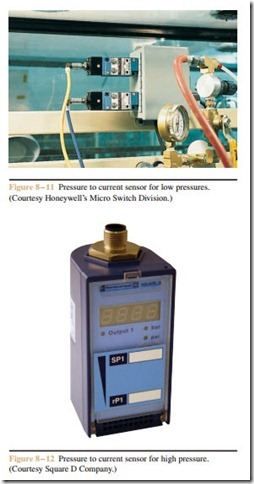
Other sensors can be obtained that produce a current output of 4 to 20 milliamperes, instead of a regulated voltage output (Figure 8 – 11). One type of pressure to current sensor, which can be used to sense pressures as high as 250 psi, is shown in Figure 8 – 12.
This sensor can also be used as a set point detector to provide a normally open or normally closed output. Sensors that produce a proportional output current in- stead of voltage have fewer problems with induced noise from surrounding magnetic fields and with volt- age drops due to long wire runs.
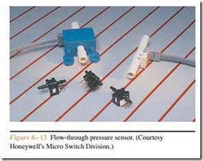
A flow-through pressure sensor is shown in Figure 8 – 13. This type of sensor can be placed in line with an existing system. In-line pressure sensors make it easy to add a pressure sensor to an existing system.
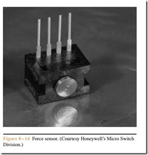
Another device that is basically a pressure sensor is the force sensor (Figure 8 – 14). This sensor uses silicon piezoresistive elements to determine the amount of pressure to the sensing element.
Review Questions
1. What type of pressure switch is generally used to sense small changes in low pressure systems?
2. A pressure switch is set to cut in at a pressure of 375 psi and cut out at 450 psi. What is the pressure differential for this switch?
3. A pressure switch is to be installed on a system with pressures that can range from 1500 psi to 1800 psi. What type of pressure switch should be used?
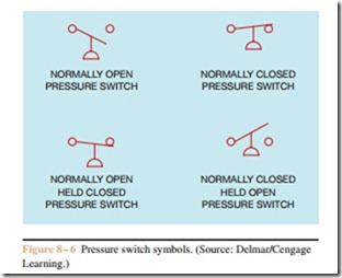
4. A pressure switch is to be installed in a circuit that requires it to have three normally open contacts and one normally closed contact. The switch actually has one normally open contact. What must be done to permit this pressure switch to operate in this circuit?
5. What is a piezoresistor?
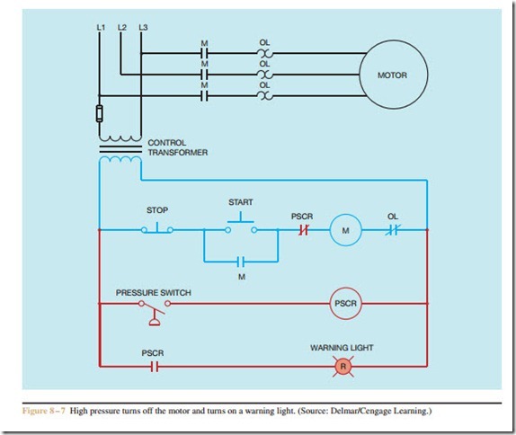
6. Refer to the circuit shown in Figure 8 – 7. If the pressure should become high enough for the pres- sure switch to close and stop the motor, is it pos- sible to restart the motor before the pressure drops to a safe level?
7. Refer to the circuit shown in Figure 8 – 7. Assume that the motor is running and an overload occurs, causing the OL contact to open and disconnect coil M to stop the motor. What effect does the opening of the overload contact have on the pressure switch circuit?
