A modern printer
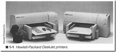
COMPUTER PRINTERS ARE AS INDISPENSABLE TO OUR modern world as automobiles, telephones, radios, or television (figure 1-1). Printers can type business or newsletters, address mail, plot drawings and illustrations , generate long listings of information, and many other boring, redundant jobs that people once had to do by hand or by typewriter. But the printer has evolved beyond the role of a simple workhorse. High-resolution and color printers have revolutionized desktop publishing , commercial art, and all aspects of engineering. Just think of what life would be like if you did not have your printer on hand. This chapter provides you with an intro duction to printer concepts, specifications, and major assemblies.
The sheer variety of printer sizes, shapes, technologies, and fea tures simply staggers the imagination. Yet in spite of all this diver sity, every printer ever made performs the same task-a computer printer is a device that transcribes the output of a computer into some permanent form. It sounds simple enough , right? In reality, however, it takes a complex interaction of electrical and mechani cal parts all working together to make a practical printer. Stop for a moment and consider some of the things that your own printer must be capable of.
First, the printer is a peripheral device (like a monitor or a mo dem). It can do nothing at all without a host computer to provide data and control signals, so a communication link must be estab lished. To operate with any computer system, the printer must be compatible with one or more standard communication interfaces that have been developed. A printer must be able to use a wide va riety of paper types and thicknesses that can include such things as multipart forms, envelopes, and specially-finished papers. It must be capable of printing a vast selection of type styles and sizes, as well as graphics images, then mix those images together onto the same page. The printer must be fast. It must communi cate, process, and print information as quickly as possible. Print ers must be easy to use-many features and options are accessible with a few careful strokes of the control panel. Paper input and output must be convenient. Expendable supplies (such as toner, ribbons, and ink) should be quick and easy to change. Finally, printers must be reliable. They must produce even and consistent print over a long working life, which can easily exceed 50 million characters (expendable items have to be replaced more fre quently). The first place to start any study of printers is to under stand their features and specifications.
Features & specifications
Make it a point to know your printer’s specifications and features before you begin any repair operation. This gives you a good idea as to what the printer is capable of, and might help you to test it more thoroughly during and after your repair. A listing of specifi cations is usually contained in an introductory portion of the owner’s manual, or at the end in an appendix.
Remember that there is no standard format for listing a printer’s specifications. It is up to the individual preferences of each manu facturer. Some specifications will be listed depending on which printing technology is in use. For example, an electrophotographic (EP) printer will be specified a bit differently than a dot-matrix impact printer. Regardless of the particular technology, however, a list of specifications will almost always contain the following points: power requirements, interface compatibility, print capac ity, print characteristics, reliability/life information, envirorunental information, and physical information. Each of these areas has some importance to a technician, so you should be familiar with them in some detail.
Power requirements
AB with any electrical device, a printer requires power in order to function. Voltage, frequency, and power consumption are the three typical specifications that you will find here. Domestic U.S. voltages can vary from 105 to 130volts ac (Vac) at a frequency of 60Hz. Eu ropean voltages can range from 210 to 240 Vac at 50 Hz. Because virtually all commercial printers are designed for global sales, de signers accommodate this variation in voltage by providing a voltage selection switch (usually located near the printer’s ac cord). The switch sets the printer’s power supply for proper operation at 120 Vac or 220 Vac. If this switch is set improperly for the local ac volt age, the printer will function erratically (if it runs at all), and can even result in damage to the printer’s power supply. The wise tech nician will always start a repair by checking for this voltage selection switch, and verifying that it is set to the proper position.Power consumption is rated in terms of watts (W). Power de mands vary widely in printer designs. Contemporary impact dot matrix printers use up to 100 W during printing. Ink printers use much less power (25 W), even less for portable ink jet models. On the other hand, EP printers require substantially more power, with peak demands exceeding 800 W. Keep in mind that power de mands are much less while the printer is idle (not actually print ing). Chapter 8 discusses the operation and repair of printer power supplies.
Interface compatibility
Remember that a printer is a peripheral device, that is, it serves no purpose at all unless it can communicate (or inteiface) with a computer. A communication link can be established in many dif ferent ways, but three predominate interface techniques have be come standard: RS 232, Centronics, and IEEE 488. Only a properly wired and terminated cable is needed to connect the printer and computer. Printer communication is discussed in Chapter 9.
RS 232 is a serial interface technique used to pass binary digits (bits) one at a time between the computer and printer. Serial links of this type are very common, not just for printers, but for other se rial communication applications such as modems and simple digital networks. RS 232 is popular due to its moderate speed, the physi cal simplicity of its wiring, and its potential to handle data over rel atively long distances. Unfortunately, serial conununication links require a surprising number of variables to be set. This makes the serial approach more difficult to configure (and adjust later).
Centronics is the standard for parallel printer conununication. It is a “de-facto” standard, so it is not officially endorsed by standards organizations such as the IEEE, EIA, or ITU. Instead of passing one bit at a time, entire characters are passed from the computer to the printer as complete sets of bits. Centronics is popular due to its functional simplicity. Even though it requires more intercon necting signal wires than an RS 232 cable, the hardware required to handle parallel information is simpler. There are also no vari ables to consider, just connect the printer to the PC and you’re on your way. While parallel ports were once the exclusive realm of printers, contemporary peripherals (i.e., external tape drive, CD ROM drive, and so on) are competing for space on the port.
IEEE 488, also known as GPIB (General Purpose Interface Bus), is an official standard for parallel communication that serves print ers and plotters, along with automated instrumentation. It is not as widely used as Centronics, but GPIB supports network and bidi rectional communication (where Centronics is traditionally a one way, single-peripheral technique). The GPIB technique was originally developed by Hewlett-Packard Company, where it is still widely used in their line of printers and plotters.
Print capacity
Print capacity is actually a set of individual specifications that outline the mechanics of a printer’s operation. Some of the character istics that you should be familiar with are: CPL, CPS, print direction, dot configuration, resolution, pages per minute, warm-up time, and paper feed.
The term CPL stands for Characters per Line, and is typically re lated to moving-carriage printers, such as impact or ink jet dot matrix printers. This is the number of characters that can fit onto a single horizontal line of text. You will likely find several entries under this heading-one for each type size (or style) that the printer can produce. A larger type size will result in fewer charac ters per line, and vice versa. For example, a type size that yields 10 CPI will fit 80 characters on an 8-inch horizontal line. At a setting of 15 CPI, 120 characters could fit on that same 8-inch line. CPL is also widely known as character pitch.
CPS means characters per second. It is also related to moving-car riage printer designs and indicates just how fast your printer will generate complete characters. This specification is closely related to character pitch, so you will probably find one entry for each pitch setting. Smaller characters that are composed of fewer dots can be produced faster, so they will have a higher CPS rate. Larger characters (or letter-quality characters) are composed of more dots, so their CPS rate will be lower.
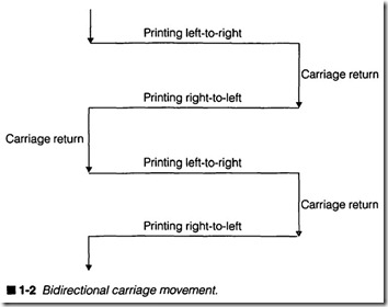
Print direction is related to moving-carriage printers, and defines the way in which a printer’s carriage can move during operation. Virtually all moving-carriage printers that produce simple text op erate in a bidirectional mode as shown in figure 1-2. The carriage moves in one direction across a page, paper advances, then the carriage moves across the page in the opposite direction. Paper advances, then the carriage moves in its original direction again. Unidirectional printing is often used for more calculation-inten sive printing applications such as bit-map graphics. The carriage moves in one direction across the page (usually left to right), the page advances, and the carriage moves back to its starting point before printing a subsequent line. Figure 1-3 shows a basic unidi rectional pattern.
Individual dots placed on a page are defined by several different specifications depending on whether the printer is working ina text or graphics mode. Moving-carriage printers typically define a dot configuration, which indicates the physical size of each dot being placed on the page. Impact dot-matrix print heads frequently provide a dot configuration of 1/127 (0.2 mm) in diameter. Ink jet print
heads often sport much smaller dot sizes. The dot alignment details how many dots are placed (vertically and horizontally) to form a character. For example, an impact printer dot alignment of 24 x 9
shows that a draft mode character is composed of up to 24 vertical dots, and 9 horizontal dots. In letter quality mode (LQ), this in creases to 24 x 30. On the other hand, an ink jet printer in draft mode runs at 50 x 15, where LQ mode offers 50 x 30. This is why many ink jet printers provide better-looking text even in draft mode.
Finally, dot pitch indicates how precisely dots can be placed in the horizontal and vertical direction. A typical impact printer can achieve a dot pitch of Ytzo11 (0.21 mm) in the horizontal direction, and Ytso 11 (0.14 mm) in the vertical direction. In other words, the im pact printer can place 120 horizontal dots per inch (dpi) and 180 vertical dots per inch. This is the printer’s graphic resolution. While some impact printers are capable of up to 360 x 360 dpi, this produces a tremendous amount of print head heat and mechanical work, which results very slow printing. From a practical perspec tive, impact printers work best at low resolution (60 x 60 dpi or so). Ink jet printers are also capable of very fine resolutions (up to 360 x 360 dpi), and they provide faster performance since the print head does not get hot. Still, the slow rate at which ink dots can be ejected limits printing speed at high resolutions. As you will see in later chapters, EP printers are not limited by such con straints, and resolutions are available from 75 x 75 dpi to 1,200 x 1,200 dpi (and higher). The “standard, operating resolution for current, low-end, commercial EP printers is 300 x 300 dpi. In the printer world, the reference to resolution always indicates that im pact or ink jet printer is working in the graphics mode (EP print ers work only in a graphics mode).
Where moving-carriage printers focus on specifications, such as characters per second and lines per inch to establish a printing rate, EP printers simply define their printing speed as pages per minute (ppm). This rate is largely determined by the printer’s me chanical design. Low-cost, low-end EP printers will work at 4 ppm, while high-cost, high-end EP models can operate at 12 ppm or higher. Keep in mind that ppm is an optimum printing rate-large graphic images might require additional time to transfer the cor responding data, which easily can slow printing.
Warm-up time is another specification applied to EP printers. Im pact and ink jet dot-matrix printers do not require warm-up time; they’re ready to go as soon as you turn the printer on. However, EP printers must melt toner to the paper. This requires the EP printer to reach a stable working temperature. When the printer is operating correctly, a working temperature can be reached in un
der 90 seconds.
Paper handling
Paper handling specifies the method(s) used to transport paper through the printer. There are two classical techniques for trans porting paper through a printer; tractor-feed and friction-feed. The tractor-feed is the most widely accepted type of mechanism for use in general-purpose or high-volume printing, especially for impact dot-matrix printers, but friction-feed is quickly growing in popu larity for single-sheet “letter-quality” printers, such as inkjet. Elec trophotographic printers use friction-feed techniques exclusively, but the EP paper handling system is far more involved than those used in moving-carriage printers (as you will see in Chapter 4).
The tractor-feed technique uses a continuous length of folded pa per with holes evenly perforated along both sides. This paper is threaded into the paper transport, and inserted into sprocket wheels located just over the platen. Teeth on each sprocket wheel mesh exactly with holes in the paper. The platen and sprocket wheels are linked mechanically, so as the platen is advanced, both sprockets tum to pull paper through evenly. Some tractor-feed configurations can be threaded somewhat differently so that pa per is pushed through the printer instead of pulled through.
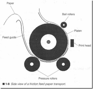
The friction-feed technique is effective for single sheets of paper. In most cases, any fresh, dry sheet of standard 20-lb bond xerog raphy-grade paper will do, though ink jet printers might require specialized inkjet paper for best results. A sheet is started into the mechanism, then locked down against the platen using one or more pressure (or “pinch”) rollers. Paper is now fixed in place. As the platen advances, friction between the platen and pinch rollers literally push the paper along. Chapter 10 discusses paper trans ports (and other mechanical systems) in more detail.
Print characteristics
Print characteristics specify the way in which printer images will appear, how they will be produced, or how characters sent from the computer will be interpreted. Font, software emulation, and character sets are the three specifications that you should be most familiar with.Ajont is essentially a style of type with certain specific visual char acteristics (sometimes very subtle characteristics) that set it apart from other type styles. Such characteristics might include differ ences in basic character formation, accents, and decorative addi tions (e.g., Courier versus Helvetica type). Figure 1-4 is an overview of several basic fonts found in impact dot-matrix or ink jet print ers. Most commercial moving-carriage printers are capable of pro ducing at least two fonts-often a simple “draft” style and a more detailed “letter-quality” style. Contemporary ink jet and laser printers are typically fitted with dozens of fonts. Printers also can produce font enhancements, such as underlining, bold, italic, su perscript, or subscript. Keep in mind that not all enhancements are available in all fonts.
There are two methods of extending a printer’s font selection. The first method is to install one or more font cartridges in the printer itself. The font cartridge is basically just a ROM that contains the data needed to form different type styles. The desired font (some times referred to as a hard-font) can then be selected from the printer’s control panel. When subsequent ASCII characters are re ceived, they will be printed using the selected font. While contem porary font cartridges are available containing dozens of fonts, the font-cartridge technique is still limited by flexibility; if you need to print in a font that’s not in the printer, you need to change the font cartridge or select an available font.
Such hardware limits are overcome using soft fonts. The soft-font technique allows the document processor in the PC (i.e., your word processor) to select the fonts used inthe document, then download those fonts from the PC hard drive to the printer. The document processor can then specify a font in the document and send along the ASCIT characters without concern for whether the font will be available or not. Of course, soft fonts have their disadvantages. The major drawback to soft fon s is their use of printer memory; each font can demand several kilobytes (KB) of printer memory. When several fonts are downloaded, you can imagine how a moving-car riage printer with only a few KB of memory could quickly be over loaded by soft fonts. It is possible to add a bit of memory to most moving-carriage printers, but the expense is rarely worth the lower print quality. AB a consequence, soft fonts are typically reserved for large-memory printers, such as EP printers.
Hard fonts and soft fonts still play a vital role in DOS-based print ing. However, it is important to realize that printer fonts are only important when the printer is working in its text mode (i.e., re ceiving ASCII characters). Windows and Win95 print exclusively in the graphics mode, so the fonts and images that appear in a printed page rely on the fonts contained in the operating system itself, not the printer. The information you see in a WYSIWYG display (what you see is what you get) for Windows applications such as Mi crosoft Publisher is translated directly to graphic data in the PC, then sent on to the printer as a graphic. This approach offers al most limitless potential for creating very sophisticated docu ments, while removing the need for any printer fonts.Of course, just sending an ASCII character to the printer is not enough; the printer has to know how to respond to that character. Printers use an internal printer language to establish and maintain standard operations. The language resides in the printer’s perma nent memory, and specifies such things as how to recognize and respond to control codes embedded in the string of ASCII charac ters. Most of the popular printer languages were originally devel oped by leading printer manufacturers, such as Hewlett-Packard, IBM, and Epson. While many printer manufacturers offer nonstan dard languages to take advantage of the particular printer’s unique capabilities, printers can almost always switch languages to achieve compatibility.
Other manufacturers that wish to make their printers functionally compatible must write their own internal software that emulates one or more of the existing language standards. As you become fa miliar with printers you will see that the Epson LQ-2500 and FX- 80, IBM Proprinter X24 and Proprinter III, Postscript, and various levels of Hewlett-Packard’s printer control language (referred to as PCL and often found in EP printers) have been embraced as “standard” printer languages. For example, a Panasonic impact dot-matrix printer might offer software emulation for an Epson LQ-2500. This means even though the Panasonic printer is physi cally and electrically different from an Epson, it will respond as if it were an Epson LQ-2500 when connected to a host computer. An Okidata EP printer will typically emulate an HP LaserJet III.
When a character code is sent to a printer, it is processed and de livered as a fully formed alphanumeric character or other special symbol. However, because a character code is not large enough to carry every possible type of text or special symbol (e.g., foreign lan guage characters or block graphics), characters are grouped into character sets that the printer can switch between. Switching a character set can often be accomplished through a series of com puter codes defined by the printer language, or control panel com mands. By switching character sets, the same ASCII code can be made to represent completely different symbols. A standard char acter set consists of 96 ASCII (American Standard Code for Infor mation Interchange) characters (26 uppercase letters, 26 lowercase letters, 10 digits, punctuation, symbols, and some control codes). Other character sets can include 96 italic ASCII characters, inter national characters (German, French, Spanish, etc.), and unique block graphics.
Reliability/life information
Reliability and life expectancy information expresses the ex pected working life of the printer or its print head in terms of pages, time, or characters. For example, a typical impact dot matrix print head can have a life exceeding 100 million characters. A good-quality electrophotographic printer could have a rated service life better than 300,000 pages. You might see this same information expressed as MTBF (Mean Time Between Failures) or MPBF (Mean Pages Between Failures). Expendable material life times are also included under this heading. Ribbon, ink cartridge, and electrophotographic cartridge life is usually quoted in terms of pages or characters.
You should realize that reliability figures are hardly absolute. A printer’s working life is greatly influenced by factors such as regu lar maintenance, the working environment, and media quality. In other words, a dot-matrix printer processing three-part forms all day long in the middle of a dirty factory floor isn’t going to last nearly as long as the same printer delivering a few dozen text pages each day in a clean, air-conditioned office.
Environmental information
Environmental specifications indicate the physical operating ranges of your printer. Storage temperature and operating temperature are the two most common environmental conditions. A typical printer can be stored in temperatures between 0°F and 100°F, but it can only be used from 50°F to 90°F (on the average). As a gen eral rule, it is a good idea to let your printer stabilize at the current
temperature and humidity for several hours before operating it. Relative humidity can often be allowed to range from 10% to 90% during storage, but it must be limited from 30% to 80% during op eration. Keep in mind that humidity limits are given as “noncon densing” values; water vapor cannot be allowed to condense into liquid form. Liquid water in the printer would certainly damage its motors and electronics. Moist paper will also result in poor print quality. Your printer might also specify physical shock or vibration limits to indicate the amount of abuse the printer might sustain be fore damage can occur. This is usually rated in terms of g-jorce. As a rule, the printer should be free of shock and vibration.
Physical information
Finally, physical information includes such routine data as the printer’s height, width, and depth, as well as its weight. In some cases, an operating noise level specification is included to indicate just how loud the printer will be while in operation and standby modes. Acoustic noise level specifications are usually given in dBA (audio decibels).
Understanding the typical assemblies
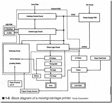
No matter how diverse or unique printers might appear from one model to the next, their differences are primarily cosmetic. It is true that each printer might use different individual components, but every printer must perform a very similar set of actions. As a result, most moving-carriage printers can be broken down into five typical subsections, or functional areas: the paper transport as sembly, the print head assembly, the print head transport (or car riage), the power supply, and the electronic control unit. These key elements are illustrated in the detailed block diagram of figure 1-5. This part of the chapter introduces you to each of those sub assemblies.
Paper transport assembly
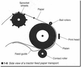
Every printer must handle paper. Paper must be picked up, car ried in front of the print head, then delivered out of the printer in tact. There are two classical methods of achieving paper transport: tractor-feed and friction-feed. Figure 1-6 illustrates a typical trac tor-feed paper transport assembly. All paths lead paper around a rubber platen (in front of the print head) and into a set of plastic sprocket wheels. Any additional rollers, such as the “bail, rollers, are used to apply light pressure, which keeps paper flat and even
against the platen. Each sprocket wheel is fitted with teeth that mesh exactly with holes perforated along both sides of the paper. Both wheels are linked together, then linked mechanically to the platen by a gear train or pulley system. When the platen advances, it will turn both sprockets an equal amount to pull paper up and out of the printer. Tractor-feed systems require some type of con tinuous fonn paper, but because paper is pulled evenly at all times, it should always feed evenly. Figure 1-7 shows you the exploded view of a typical tractor-feed paper transport assembly.
A friction-feed paper transport system is shown in figure 1-8. A mechanical lever is often used to pry pressure rollers away from the platen while paper is being threaded and aligned . When the lever is released , pressure rollers are brought into tight contact with the paper and platen. As the platen advances, contact forces between the platen and rollers move the paper through. Bail rollers only serve to keep paper flat and even against the platen as paper leaves the printer.
Friction-fe ed systems can useju st about any single-sheet, medium weight paper or multipart form. This can make friction feed very flexible, but not without its problems . Because paper is clamped into place under pressure , it will invariably travel the direction in which it is clamped. If paper is not perfectly straight, it will “walk” to the left or right as the platen advances. Even if the sheet was in serted straight, old or misaligned rollers can cause walking.
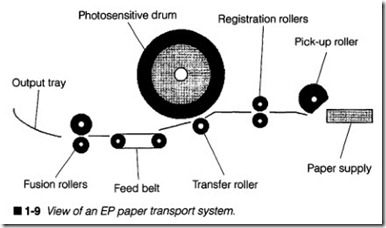
A variation of the friction-feed system can be found in most elec trophotographic printers as shown in figure 1-9. Conventional fric tion-feed printers require you to insert and align single sheets of
paper, one at a time. An EP paper feed system uses a notched rub ber pick-up roller to grab individual sheets as needed from a cen tral paper tray. Paper is always started reasonably straight because of its alignment by the tray. A set of registration rollers holds the sheet stationary until an image is prepared on a photosensitive EP drum. At that point, registration rollers push the paper to the drum where its image is transferred to paper. A feed belt gently carries the page to a set of heated fusing rollers, which fix the im age permanently. Chapter 4 presents a much more complete ex amination of EP printing technology.
Print head assembly
A print head is a discrete device responsible for actually applying permanent print to the page surface. Four major technologies have evolved to accomplish this process: impact, thermal, ink jet, and electrophotographic. Printers are typically categorized by the par ticular technology that they use (e.g., thermal dot-matrix printer, ink jet dot-matrix printer, and so on). As discussed later, however, EP printers form images through a process rather than a print head.
Impact technology is just what the name implies; characters, sym bols, and (sometimes) graphics are literally struck onto a page surface through an inked ribbon of fabric or plastic. The force of impact leaves an ink impression of whatever was to be printed. You might encounter two types of impact print heads: the character print head and the dot-matrix print head.
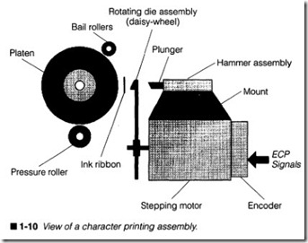
Character print heads (also called daisy wheels) are the simplest and most straightforward type of print head design, as shown in figure 1-10. Modeled after a conventional typewriter, a daisy wheel is little more than a print wheel containing a fixed selection of preformed letters, numbers, pllllctuation, or other symbols. Each is reverse molded onto a single plastic support structure. When an ASCII char acter is received, the print wheel rotates so that the desired character is positioned in front of the platen. The character is then rammed against the page by a solenoid. Impact takes place through an inked ribbon, so the character’s image is transferred to the page.
Although the daisy-wheel printer produced some excellent print, the drawbacks were easy enough to recognize. First, the continu ous spinning and ramming of the daisy wheel created a serious clatter. Also, mechanical limitations of the daisy wheel limited the printer’s maximum printing speed. Constant flexing of daisy wheel “petals” frequently resulted in broken print wheels; so regular print-wheel replacement was a must. Next, the print size and font was static, so it was impossible to select different fonts or type sizes without replacing the daisy wheel (graphics were out of the question). Character printers have long since been obsoleted by dot-matrix designs, and it is highly unlikely that you will ever fmd a character printer still in service. This book will not cover charac ter printers further.
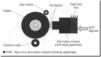
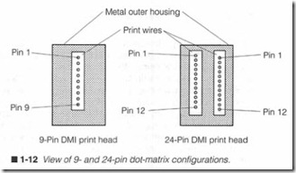
The impact dot-matrix print heads use a series of individual metal wires arranged in a vertical pattern as shown in figure 1-11. Each wire is operated by its own small solenoid, which can be driven in dependently. By firing groups of print wires in predetermined combinations, any letter, number, symbol, or graphic image can be produced while a dot-matrix head moves across the page. Impact occW”s through an inked ribbon, so the image is transferred to pa per. Figure 1-12 shows some typical dot formations for 9- and 24- pin prin t heads. The face of an impact dot-matrix print head can be flat or slightly curved to match the radiu s of a platen. Print wires are ground flat against the print head’s face once they are in stalled to ensme an even and consistent dot formation for every print wire.
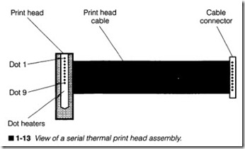
While impact dot-matrix print heads offer the versatility and relia bility that daisy wheels do not, the technology also suffers from some drawbacks. First, impact print heads need a substantial amooot of energy to operate. This demands a relatively large power supply, and the print head becomes extremely hot during operation. Dot matrix printing is not terribly fast. Per-character printing rates are faster than those of daisy wheels, but to achieve a comparable quality print, the dot-matrix head might have to make several passes to complete a single line of text. Impact dot-matrix printers also make a great deal of noise. The high-frequency chatter of con tinuous wire impacts can become very annoying.Thermal dot-matrix print heads overcome some of the limitations of impact print heads. A serial thermal print head is shown in fig ure 1-13. Instead of physically moving print wires in and out, a thermal print head uses an array of microscopic heater elements. An electrical pulse from driver circuits will cause a dot heater to warm very quickly. This leaves a corresponding dot on the page surface. As with impact dot-matrix heads, an array of dot heaters can be fired in any desired sequence to produce virtually any let ters, numbers, or graphics. Because there are no moving parts in the print head, its operation is totally silent.
An alternative to a serial (or moving) thermal print head is the line-head technique shown in figure 1-14. Aline-head is essentially a thermal print bar. It contains a horizontal row of dot heaters one heater for every possible dot along a horizontal line. Instead of a vertical column of dots forming full characters as the head moves across a page, an entire line of text or graphics can be formed one 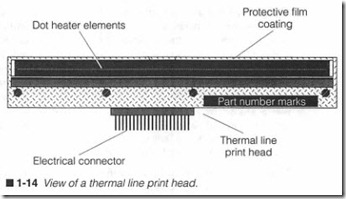
row at a time. Line-head printers offer the advantage of simplicity; no carriage transport assembly is needed to carry a print head back and forth. Facsimile machin es typically use thermal line head printing.Thermal print head technologies have proven to be a handy, reli able, and quiet alternative to impact print heads, but there are some serious trade-offs. Because a finite amount of time is re quired to heat and cool a heater element, thermal printing is a rel atively slow process. Thermal printing is also limited to a single pass (such as fax printing), so the print is generally quite legible, but its overall appearance is poor. Another strike against thermal print heads is their need for heat-sensitive paper, which has proven to be fragile, expensive, and hard to handle or store. Nor mal paper could not be used because the temperatures required to mark normal paper would burn it. This restriction can be over come by using a “transfer” version of a thermal print head (serial or line). Instead of the head actually contacting a page, a transfer ribbon is inserted between the two. The head heats corresponding points of wax on the transf er ribbon that melt onto the page. While this mad e thermal printing a bit more practical for “plain paper” printers, the technology never really gained broad acceptance.
Ink jet dot-matrix print head technology evolved to offer an alter native method of quick, quiet, inexpensive printing that would provide print quality superior to impact print heads and still work on almost any type of paper. This method of printing draws liquid ink from a central reservoir, then “spray paints” the desired char acters or graphics onto a page surface through a series of inde pendent nozzles. Ink jet printing speeds can easily match that of an impact dot-matrix printer. There are two primary methods of commercial ink jet printing: piezoelectric jet and bubble jet (also called thermal jet).
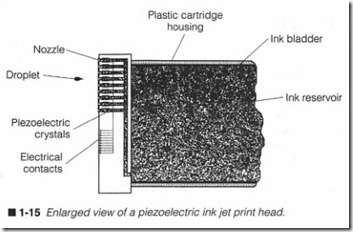
A piezoelectric jet print head uses liquid ink from a small, local reservoir to fill a series of ink channels illustrated in figure 1-15. While older ink jet heads typically provided 9 or 24 ink channels, contemporary ink j et heads can provide 50 ink channels or more . Each channel is covered by a nozzle, which is nothing more than a microscopic hole drilled into a metal plate. A small piezoelectric crystal in each chann el acts as an “ink pump.” A short, high-energy pulse from the printer’s driver circuits vibrates the crystal, which ejects a single droplet of ink from the corresponding nozzle.
Bubble j et print heads are very similar to piezoelectri c je t devices, but the resonating piezoelectric crystals are replaced by small heater elements. An electrical driver pulse heats ink in a channel. A bubble forms and expands until it bursts. The force of a bursting bubbl e ejects a droplet of ink from the nozzle.
Modern ink jet print heads offer an astounding mix of advantages . They require relatively little power (an ideal attribute for mobile printers), yet they can generate high-quality text and graphics at resolutions that rival EP printers. Ink jet operation can be slow when printing high-resolution graphics, but the low cost and dis posable print head design often makes the trade-off worthwhile. Ink jet technology has also been adapted to inexpensive color printing. A remaining disadvantage of ink j et technology is the need for specialized paper; most standard papers will work, but clay-coated papers provide the best ink drying characteristics.
The electrophotographic printing techniq ue is radically different from any of the previous print technologies. As you will see in Chapter 4, an electrophotographic (EP) “print head” is actually a combination of devices that incorporate light, static electricity, chemistry, optics, heat, and pressure to place a permanent image on a page. Images are formed as an array of dots written to a light sensitive drum. A laser beam has been used to write dots, but they are rapidly being replaced by smaller, lighter, and more reliable writing devices. EP printing offers many advantages over other technologies; it is fast and quiet, it works at resolutions up to 1,200 x 1,200 dpi and higher, and it works with single sheets of paper.
Print head transport (carriage)
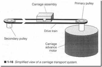
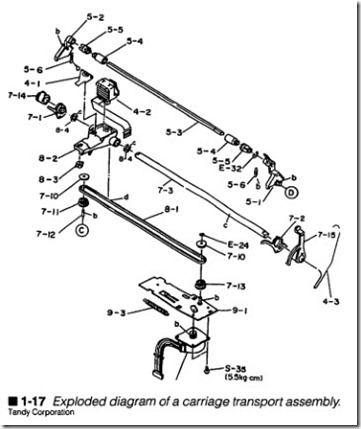
Most serial print heads only provide a single vertical column of dots. As a result, the print head must be carried back and forth across the page to form characters, words, and sentences. This movement is accomplished by a print head transport mechanism (also known as a carriage). A basic head transport system is shown in figure 1-16. The key assembly here is a slide that is free to move along a set of rails. The print head itself mounts securely to the carriage with either a series o£ screws or tight hold-down clips. A simple pulley system driven by a stepping motor is used to supply the left/right motion through a belt or threaded rod. Figure 1-17 presents an exploded view of an actual carriage transport.
Two sensors are usually incorporated into the head transport sys tem (not shown in figures 1-16 or 1-17). A print head home sensor is located at the left end stop. This tells the printer’s electronics when a carriage has reached its home position. An optical encoder is often added to the motor assembly. It sends distance and direc tion information back to the control electronics that allows con stant monitoring of the print head’s current location.
Power supply
A power supply is responsible for converting ac line voltage into one or more of the de voltage levels that are needed by the printer’s electronic and electrical components. Typical voltage outputs are 5, 12, and 24 Vdc. High-voltage supplies used in elec trophotographic printers can provide ionizing voltage levels of -6,000 V or more. There are both linear and switching power sup plies. Each is distinguished by the method used to control output voltages. Linear supplies are relatively straightforward devices as discussed in Chapter 8. They are simple to understand and trou bleshoot, but they are inefficient. Switching supplies can be much more complex to follow and repair, but they are smaller, and can be very efficient.
Electronic control unit
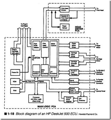
The electronic control unit (ECU) represents a combination of electronic components and circuits that direct every detail of a printer’s operation. A typical ECU is made up of five major sec tions: a communications interface, driver circuits, a control panel, memory, and main logic. In spite of the diversity between printers and print head technologies, every printer model must include cir cuitry to handle these areas. Figure 1-18 illustrates each of these key areas in the ECU for an HP DeskJet 500 printer. The exploded diagram of figure 1-19 shows you the ECU (marked 19), the sepa-rate head driver circuit (marked 15), and the system power supply module (marked 17) in the overall DeskJet assembly. The detailed operation and troubleshooting techniques for an ECU are pre sented in Chapter 9.
A communications interface handles the transfer of all data be tween the printer and computer. It also manages and coordinates signals (“handshaking”) that synchronize data transfer. Data can be transferred over either a “parallel” or “serial” interface. Both in terface methods work equally well for most general-purpose print ers. Your printer’s particular compatibilities are listed in its user’s manual. Digital electronics alone is not enough to run a printer.
Drivers convert low-power digital signals into voltage and current levels that are needed to operate real-world devices, such as mo tors, solenoids, and print heads. Drivers also might be used to con dition sensor signals for use by digital logic.
A control panel allows you to work with the printer directly by op erating manual functions (e.g., line feed, form feed, etc.). It also lets you alter various operating modes like font style or character pitch. Indicators are included to display various printer conditions.Your printer’s overall operation is organized and managed by the main logic circuits. Decision making is handled by programmable processing components such as microprocessors or microcontrollers. There might be more than one processing component depending on the printer’s sophistication. New printers tend to replace a sec ond microprocessor with one or more application-specific inte grated circuits (ASICs), which can optimize printer communication and driver functions. Memory devices are needed to retain perma nent and temporary information used within the printer. The printer’s command language and microprocessor instructions are stored in permanent memory (ROM). Temporary memory (RAM, also called the buffer) is used to hold character and graphic data received by the printer’s communication interface.
