 THE TRANSFORMER VOLTAGE REGULATION AND EFFICIENCY
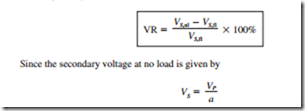
The transformer’s output voltage varies with the load even when the input voltage remains constant. This is due to the fact that a real transformer has impedances within it. The volt- age regulation (VR) is used to compare the voltage variations in transformers. The full- load voltage regulation is a parameter that compares the transformer’s output voltage at no load with the output voltage at full load.
The Transformer Phasor Diagram
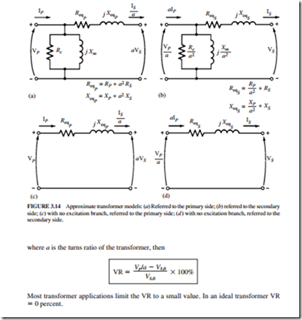
Figure 3.13 illustrates a simplified equivalent circuit for a transformer. The excitation branch (Rc and Xm) has a negligible effect on the voltage regulation of the transformer. The secondary voltage of the transformer depends on the magnitude of the series impedances within it and on the phase angle of the current flowing through it.
The primary voltage of the transformer is given by
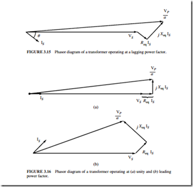
FIGURE 3.16 Phasor diagram of a transformer operating at (a) unity and (b) leading power factor.
Figure 3.15 illustrates a phasor diagram of a transformer operating at a lagging power factor. It is easy to notice that Vp /a > VS. Thus, the voltage regulation of a transformer with lag- ging loads is greater than zero.
Figure 3.16a illustrates a phasor diagram of a transformer having a power factor of 1. The secondary voltage is again lower than the primary voltage. Thus, the voltage regulation is greater than zero. However, in this case, the voltage regulation is smaller than it was in the previous case (for a lagging current). The secondary voltage will actually be larger if the secondary current is leading (Fig. 3.16b). In this case, the transformer will have a negative voltage regulation.
Simplified Voltage Regulation
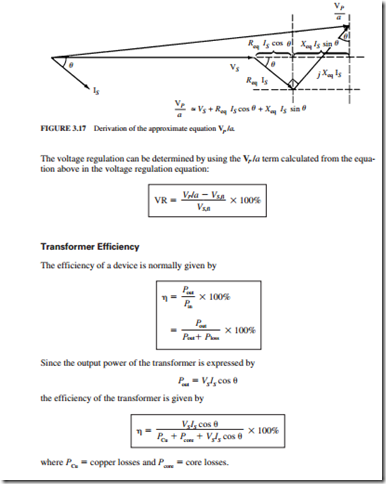
Figure 3.17 illustrates a phasor diagram of a typical transformer operating with a lagging load. The primary voltage is given approximately by
Transformer Taps and Voltage Regulators
Since the transformer’s output voltage varies with the load, most distribution transformers use taps in the windings to change the turns ratio of the transformer. Most applications have four taps with spacings of 2.5 percent of full voltage between them in addition to the nominal setting. This arrangement permits a 5 percent adjustment above or below the nominal voltage rating of the transformer.
The taps are adjusted normally when the transformer is deenergized. However, in some applications, the transformer output voltage varies significantly with the load. These variations could be caused by large line impedance (possibly due to long distance) between the generator and the load. Since normal loads require a steady voltage, these applications use a tap changing under load (TCUL) transformer or voltage regulator. This transformer has the ability to change the taps on power. A voltage regulator is a TCUL transformer that detects the voltage and changes the taps automatically to maintain constant system voltage.
Related posts:
Incoming search terms:
- voltage regulation and efficiency of a transformer
- effect of output power on efficiency and regulation
- voltage regulation and efficiency of transformer
- what is regulation and efficiency of a transformer
- voltage transformer test equipment mail
- efficiency and regulation of transformer
- define efficiency and regulation of transformer
- zero voltage regulation of transformer
- transformer voltage regulation and efficiency
- efficiency and regulation of a transformer
- efficiency and regulation in transformer
- define efficiency and voltage regulation of transformer
- voltage regulations in transformers
- transformer regulation
- voltage regulation of transformer is given by
- effect of output power on efficiency and regulations
- diagram of efficiency of transformer
- describe different factors affecting the regulation of transformer
- Relation of efficiency and regulation
- relation between voltage regulation and efficiency
- efficiency and percentage regulation of transformer
- In a transformer zero voltage regulation at full load is
- Efficiency and voltage regulations of transformer
- explain voltage regulation of a transformer efficiency
- phazor diagram of transformer at no load unity power factor lagging leading
- phasor diagram of transformer under lea
- phasor diagram of power factor zero transformer
- factor affect voltage regulation
- percentage regulation of transformer
- Explain the voltage regulations and efficiency of transformer in brief
- explain the voltage regulation and efficiency of a transformer
- factors affecting the regulation of transformer
- efficiency and voltage regulation term
- does voltage regulation of transformer effect efficiency
- zero voltage regulation unity transformer
- defin efficiency and voltage regulation of transformer
- define regulation and efficiency of a transformer
- define regulation and efficiency of transformer
- define regulation and efficiency of transformer?
- define the voltage regulation and efficiency of a transformer
- define voltage regulation efficiency of a transformer
- Effeciency and voltage regulation of transformer
- effect of lagging and leading power factor on efficiency of transformer
- effect of leading power factor on transformer
- effect of output power on regulation
- effect of voltage regulation in transformer
- effect voltage regulation on efficiency
- efficeiency and percentage regulation of transformer
- efficency and voltage regulation of transformer
- Efficiecy regulation of transformer when full load


