THE EQUIVALENT CIRCUIT OF A TRANSFORMER
Any accurate model of transformer behavior should show the losses that occur in real trans- formers. The major items that should be considered in such a model are
1. Copper losses. These are the resistive losses in the primary and secondary windings of the transformer. They are proportional to the square of the current in the windings.
2. Eddy current losses. These are the resistive heating losses in the core of the transformer.
They are proportional to the square of the voltage applied to the transformer.
3. Hysteresis losses. These are associated with the rearrangement of the magnetic domains in the core during each half-cycle. They are a nonlinear function of the voltage applied to the transformer.
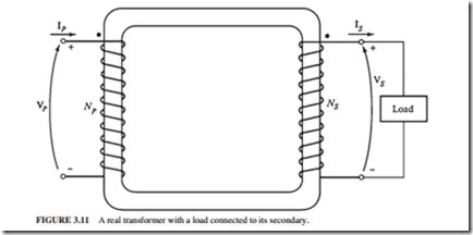
4. Leakage flux. These fluxes LP and LS pass through only one winding, escaping the core. A self-inductance in the primary and secondary windings is associated with these escaped fluxes. The effects of these inductances must be included in any trans- former model.
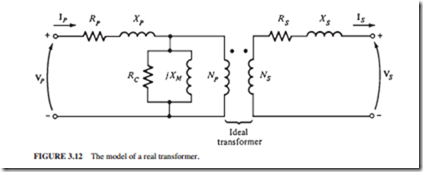
The copper losses can be modeled by placing resistors RP and RS in the primary and secondary circuits, respectively.
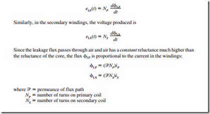
A voltage eLP is produced by the leakage flux in the primary windings LP. It is given by
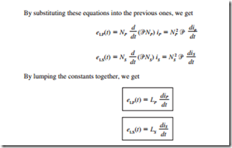
where LP and LS are the self-inductances of the primary and secondary windings, respectively. Therefore, the leakage flux will be modeled as an inductor.
The magnetization current Im is proportional (in the unsaturated region) to the voltage applied to the core but lags the applied voltage by 90°. Hence, it can be modeled as a reactance Xm connected across the primary voltage source.
The core-loss current Ih e is proportional to the voltage applied to the core and in phase with it. Hence, it can be modeled as a resistance Rc connected across the primary voltage source. Figure 3.12 illustrates the equivalent circuit of a real transformer.
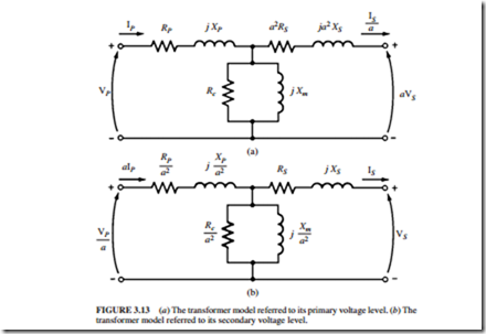
Although Fig. 3.12 represents an accurate model of a transformer, it is not a very useful one. The entire circuit is normally converted to an equivalent circuit at a single voltage level. This equivalent circuit is referred to its primary or secondary side (Fig. 3.13).
Approximate Equivalent Circuits of a Transformer
In practical engineering applications, the exact transformer model is more complex than necessary in order to get good results. Since the excitation branch has a very small current compared to the load current of the transformers, a simplified equivalent circuit is produced.
The excitation branch is moved to the front of the transformer, and the primary and secondary impedances are added, creating equivalent circuits (Fig. 3.14a and b). In some applications, the excitation branch is neglected entirely without causing serious error (Fig. 3.14c and d).
Related posts:
Incoming search terms:
- transformer equivalent circuit model
- why leakage flux is modeled as an inductor in a transformer
- why is the leakage flux modeled in a transfotmer equivalent circuit as an inductor
- how are the excitation current and leakage flux modeled in the transformer equivalent circ
- how excitation current are modeled in equivalent ckt of transformer
- transformer equivalent ckt and leakage flux inductor
- why leakage flux is modelled as inductor in transformer
- why leakage flux modelled as an inductor
