THE AUTOTRANSFORMER
In some applications, small adjustments in voltage are required. For example, the voltage may need to be increased from 110 to115 V or from 13.2 to 13.6 kV. These changes could be necessary to accommodate reductions in voltage that occur in power systems far from the gen- erators. In these cases, it would be very expensive to have two full windings in the transformer. The autotransformer is used in these applications instead of the conventional transformer.
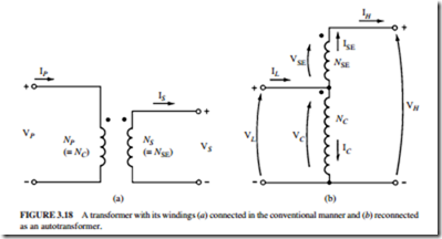
Figure 3.18 illustrates a diagram of a step-up transformer. The two windings are arranged in a conventional manner in Fig. 3.18a. Figure 3.18b illustrates the connection of the two windings in an autotransformer. The two windings are now connected in series. The turns ratio of the autotransformer determines the relationship between the voltages on the first and second windings. The output voltage of the transformer is the sum of the volt- ages on the first and second windings. The first winding in the autotransformer is called the common winding. Its voltage appears on both sides of the transformer. The second winding is normally smaller than the first. It is called the series winding.
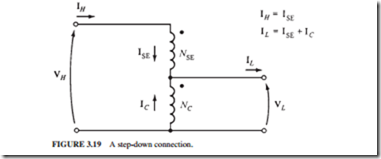
Figure 3.19 illustrates a step-down autotransformer. The input voltage is the sum of the voltages on the series and common windings. The output voltage is only the voltage on the common winding.
The terminology used for autotransformers is different from that for conventional common voltage transformers. The voltage on the common coil is VC and the common current
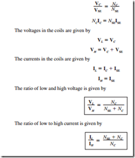
VSE. The current in this coil is called the series current ISE. The current and voltage on the high-voltage side of the transformer are called IH and VH, respectively. The corresponding parameters on the low-voltage side are called IL and VL, respectively. From Fig. 3.18b, the voltages and currents in the coils are related by:


