HOLLEY 2300 CARBURETOR OVERHAUL
Disassembly
Fuel Bowl & Metering Block
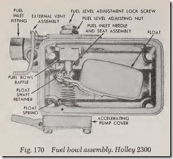
1. Referring to Fig. 170, unfasten screws and slide fuel bowl and metering block off m ain body. Separate metering block from fuel bowl and discard gaskets. Rem ove baffle from metering block.
2. Remove idle adj usting screws from metering block. Using a socket wrench, remove power valve and gasket. Remove main jet s with a suitable wrench.
3. Remove fuel level adjusting lock screw and gasket. Turn adjusting nut counterclockwise and remove locknut and gasket . R emove fuel inlet needle and seat.
4. Using needle nose pliers, remove Boat re tainer. Slide Boat off shaft. Remove spring from Boat.
5. Remove baffle plate from fuel bowl.
6. Remove external vent, Fig. 171.
7. Remove fuel level sight plug and gasket, fuel inlet fitting, gasket and filter screen.
8. Invert fuel bowl and remove accelerating pump cover, diaphragm and spring. The pump inlet ball check is not removable.
Main Body
1. Remove ah cleaner anchor stud. Invert car buretor and remove throttle body and discard throttle body gasket.
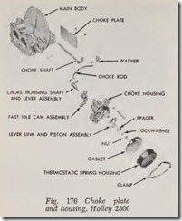
2. Remove rod from choke housing shaft and lever assembly. Remove thermostat spring h ousing and gasket, then remove choke hous ing and gasket from body.
3. Remove choke housing shaft and fast idle cam assembly. Remove choke piston and lever.
4. R emove retaining pin from choke plate shaft lever, th en remove choke rod. Remove choke plate from its shaft, then slide shaft and lever out of choke plate housing. Remove choke rod seal.
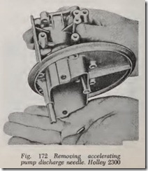
5. R emove accelerating pump discharge nozzle scr_ew, then lift pump discharge nozzle and gasket out of main body. Invert main body and let pump discharge needle fall out, Fig. 172.
Throttle Body
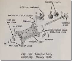
1. Remove anti-stall dashpot (if equipped). Re move accelerating pump operating lever. Re move fast idle pick-up lever and fast idle cam lever and spring.
2. If it is necessary to remove throttle plates, lightly scribe both plates along throttle shaft and mark each plate and its corresponding bore with a number or letter for proper re placement. Remove screws and throttle plates. Slide throttle shaft out of throttle body and remove accelerating pump cam.
Assembly
Make sure all holes in the new gaskets are properly punched and that no foreign material has adhered to the gaskets. Make sure the accel erating pump diaphragm is not torn or cut.
Throttle Body
1. If throttle plates were removed, refer to Fig.173. Place accelerating pump cam on throttle shaft, then slide throttle shaft into throttle body.
2. Position throttle return spring so that small tang fits into slot in throttle lever and long tang rests against wide open throttle stop.
3. Referring to marks made on throttle plates when disassembled, install plates in proper position with screws snug (not tight).
4. Hold throttle body up to the light. Little or no light should show between throttle plates and throttle bores. If plates are properly in stalled and there is no binding when the throttle shaft is rotated, tighten screws and stake them.
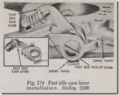
5. Place fast idle cam pick-up lever spring inside fast idle cam pick-up lever and position lever on throttle shaft so that longest end of spring rests on longest arm of pick-up lever, Fig. 174. Install screw and lockwasher.
6. Install anti-stall dashpot (if equipped) and accelerating pump operating lever and re tainer.
Main Body
1. Drop accelerating pump discharge needle into its well, Fig. 175. Seat needle with brass drift and a light hammer. Make sure it is free. Position pump nozzle gasket and nozzle in main body, then install retaining screw.
2. Referring to Fig. 176, place choke plate in air horn, then position choke plate in shaft. In stall and stake retaining screws.
3. Install choke plate rod seal in retaining grooves on main body. Slide choke plate rod through opening in main body and secure it to choke lever with cotter pin.
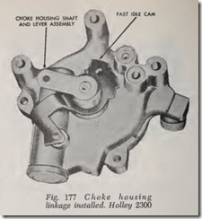
4. Install fast idle cam assembly on brass bushing on back of choke housing with bushing on cam facing outward, Fig. 177.
5. Position piston and lever in choke housing, then install choke housing shaft and lever and secure lever and piston to it with spacer, lock washer and nut.
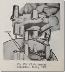
6. Lay main body on its side and position choke gasket on passages on main body, Fig. 178.
7. Position screws in choke housing. Place choke housing on main body, inserting choke rod in housing lever as housing is placed in posi tion. Be sure projection on choke rod is placed und er fast idle cam so that cam will be lifted when choke plate is closed.
8. Using needle nose pliers, install choke rod retaining pin.
9. Place thermostat spring housing and gasket in position on choke housing, engaging thermo stat spring on spring lever. Position spring housing to one notch in rich direction from th e mid-position mark , th en install clamp and screws.
10. Invert main bod y and position throttle body gasket on main body . Place throttle body on main body and secure with screws and lock washers. Install air cleaner anchor stud.
Fuel Bowl & Metering Block
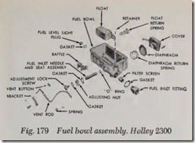
1. Referring to Fig. 179, place pump diaphragm spring and diaphragm in pump chamber. In stall cover with screws finger tight. Make sure diaphragm is centered, then compress diaphragm with pump operating lever and tighten cover screws.
2. Install fuel level sight plug and gasket, fuel inlet filter screen, gasket and fitting.
3. Install fuel bowl vent, Fig. 171.
4. Slide bailie plate on ridges in fuel bowl.
5. Install spring on float and slide float on shaft.
Using needle nose pliers, install float retainer.
6. Apply vaseline to a new “0” ring seal and slide it on fuel inlet needle and seat assembly.
7. Position fuel inlet needle and seat through top of bowl. Align flat in I.D. of nut with flat on O.D. of fuel inlet needle and seat. Ad just needle so that there is 1 ” clearance be tween floor of fuel bowl and bottom of float with fuel bowl inverted.
8. Install fuel level adjusting lock screw and gasket.
9.Install power valve and gasket, main jets, idle fuel adjusting needles and gaskets. Tum idle adjusting needles in gently until they just touch seat, then back them off % to H turns for a preliminary idle adjustment.
10. Referring to Fig. 180, position metering block gasket on dowels on back of metering block. Lay metering block in place on main body. Position bailie on metering block, then place fuel bowl gasket on metering block.
11. Place retaining screws and new compression
gaskets in fuel bowl. Lay bowl on metering block and tighten retaining screws.
ADJUSTMENTS
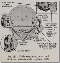
See Fig. 181 for location of idle, accelerating pump stroke and anti-stall dashpot adjustments. Adjust the idle mixture and engine speed as out lined previously in the Fuel System Service sec tion of this chapter. Adjust the anti-stall dashpot as directed to establish a clearance of .045″.
Fuel Level
1. Position car on a level floor.
2. Operate engine until normal temperature is reached. Remove air cleaner.
3. Place a suitable container below fuel level sight plug to collect any spill-over of fuel, Fig. 182.
4. With engine stopped, remove fuel level sight plug and check fuel level. Fuel level within bowl should be at the lower edge of sight plug opening within plus or minus 1/16″.
5. If the level is too high, drain the fuel bowl and refill it before altering the float setting. This will eliminate the possibility of foreign mate rial causing a temporary flooding condition. To drain the bowl, remove one lower retaining screw and allow the bowl to drain. Install the screw, start the engine to fill the bowl. After the fuel level has stabilized, stop the engine and check the fuel level.
6. To adjust the level, loosen lock screw on top of fuel bowl just enough to allow rotation of the adjusting nut underneath. Turn adjusting nut as required to obtain proper fuel level. A 1/6 turn of the adjusting nut will change fuel level at the sight plug opening by 3/64″.
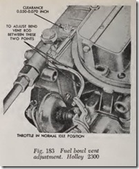
Fuel Bowl Vent
Refer to Fig. 183 and adjust the bowl vent valve as directed. The clearance shown should be estab lished between the vent button and the machined surface of the fuel bowl with the throttle in the normal idle position.
