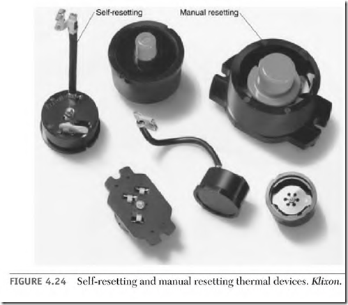
Thermal protective devices are used to protect a motor from burnout caused by overload and failure to start. There are two types, manual resetting and self-resetting. Both types have a bimetal component that bends in a predetermined direction when overheated from excessive current (Fig. 4.24).
Manual resetting thermal devices must cool before they can be reset. (Larger thermal devices may take 10 to 15 minutes to cool sufficiently.) There is a definite snap when they reset. They should be in a convenient location. If they are mounted in a motor’s connection box, they can be relocated.
A self-resetting thermal device will reset itself and start the motor when it cools. Machinery that can cause injury shouldn’t have motors with selfresetting protective devices.
Components of the Bimetal Thermal Protective
Devices (for Single-Phase Motors)
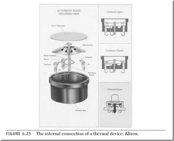
This type of protective device has a disc and two sets of contacts. Thro of the contacts are mounted on the movable part of the disc. The two mating contacts are mounted on the stationary part of the device.
Figure 4.25 shows the circuitry of a thermal device. The terminal marked PI (on the thermal device) is connected to one of the stationary contacts. A
lead in the motor’s connection box (labeled PI) is connected to this terminal. If the motor has a connection board, PI is soldered to a bolt, marked Pl. PI (as a lead or bolt) is always connected to line 1. All of the circuitry of the thermal device and the motor are in series with Pl.
The P 2 terminal is connected to the stationary contact across the disc from Pl. If the motor has a connection box, P2 is a brown wire and may or may not be marked P2. If the motor has a terminal board with connecting bolts, there’s also a bolt labeled P2.
Current through P2 has no effect on the function of the thermal device. (It disconnects when the device trips off.) If the lead P2 isn’t used in the connection, it must be insulated.
A small heat element (located near the disc) is connected between P2 and P3. When there’s an overload, higher than normal current flows through the heat element and P3. The heat element gets hot, making the disc bend, disconnecting all motor circuits. (P3 is always connected to a winding that is affected by an overload.)

