The Transistor
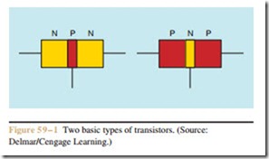
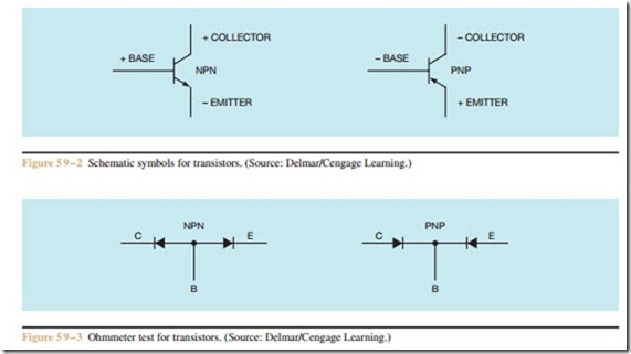
Transistors are made by connecting three pieces of semiconductor material. There are two basic types of transistors: the NPN and the PNP (Figure 59 – 1). The schematic symbols for these transistors are shown in Figure 59 – 2. These transistors differ in the manner in which they are connected in a circuit. The NPN transistor must have a positive voltage connected to the col- lector and a negative voltage connected to the emitter.
The PNP must have a positive voltage connected to the emitter and a negative voltage connected to the collector. The base must be connected to the same polarity as the collector to forward bias the transistor. Notice that the arrows on the emitters point in the direction of conventional current flow.
transistor, see Procedure 2 in the Appendix.) If the polarity of the output of the ohmmeter leads is known, the transistor can be identified as NPN or PNP. An NPN transistor will appear to an ohmmeter to be two diodes with their anodes connected. If the positive lead of the ohmmeter is connected to the base of the transistor, a diode junction should be seen between the base- collector and the base-emitter. If the negative lead of
the ohmmeter is connected to the base of an NPN transistor, there should be no continuity between the base-collector and the base-emitter junction.
A PNP transistor will appear to an ohmmeter to be two diodes with their cathodes connected. If the negative lead of the ohmmeter is connected to the base of the transistor, a diode junction should be seen between the base-collector and the base-emitter. If the positive ohmmeter lead is connected to the base, there should be no continuity between the base-collector or the base- emitter.
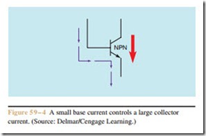
The simplest way to describe the operation of a transistor is to say that it operates like an electric valve. Current will not flow through the collector-emitter until current flows through the base-emitter. The amount of base-emitter current, however, is small when com- pared to the collector-emitter current (Figure 59 – 4). For example, assume that when 1 milliamperes of cur- rent flows through the base-emitter junction, 100 mA of current flow through the collector-emitter junction. If this transistor is a linear device, an increase or de- crease of base current will cause a similar increase or decrease of collector current. Therefore, if the base cur- rent is increased to 2 milliamperes, the collector current will increase to 200 milliamperes. If the base current is decreased to 0.5 milliamperes, the collector current will decrease to 50 milliamperes. Notice that a small Figure 59–4 A small base current controls a large collector current. (Source: Delmar/Cengage Learning.)
change in the amount of base current can cause a large change in the amount of collector current. This permits a small amount of signal current to operate a larger de- vice such as the coil of a control relay.
One of the most common applications of the transistor in industry is that of a switch. When used in this manner, the transistor operates like a digital device instead of an analog device. The term digital means a device that has only two states, such as on and off. An analog device can be adjusted to different states. An example of this control can be seen in a simple switch connection. A common wall switch is a digital device. It can be used to turn a light on or off. If the simple toggle
switch is replaced with a dimmer control, the light can be turned on, off, or it can be adjusted to any position between on and off. The dimmer is an example of analog control.
If no current flows through the base of the transistor, the transistor acts like an open switch and no cur- rent can flow through the collector-emitter junction. If enough base current is applied to the transistor to turn it completely on, it acts like a closed switch and permits current to flow through the collector-emitter junction. This is the same action produced by the closing contacts of a relay or motor starter, but, unlike a transistor, a relay or motor starter cannot turn on and off several thousand times a second.
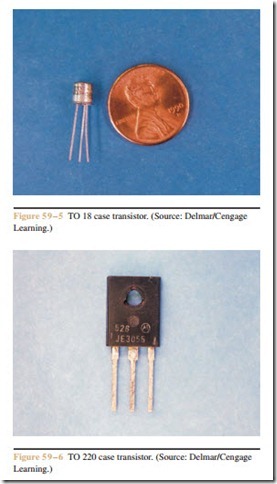
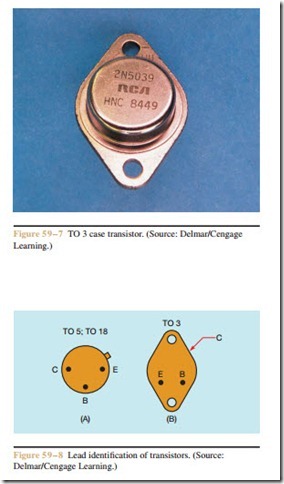
Some case styles of transistors permit the leads to be quickly identified (Figures 59 – 5, 59 – 6, and 59 – 7). The TO 5 and TO 18 cases, and the TO 3 case are in this category. The leads of the TO 5 and TO 18 case transistors can be identified by holding the case of the transistor with the leads facing you as shown in Figure 59 – 8A. The metal tab on the case of the transistor is closest to the emitter lead. The base and collector leads are positioned as shown.
The leads of a TO 3 case transistor can be identified as shown in Figure 59 – 8B. When the transistor is held with the leads facing you and down, the emitter is the left lead and the base is the right lead. The case of the transistor is the collector.
Review Questions
1. What are the two basic types of transistors?
2. Explain how to test an NPN transistor with an ohmmeter.
3. Explain how to test a PNP transistor with an ohmmeter.
4. What polarity must be connected to the collector, base, and emitter of an NPN to make it forward biased?
5. What polarity must be connected to the collector, base, and emitter of a PNP transistor to make it forward biased?
6. Explain the difference between an analog device and a digital device.
