Just as the magnetic starter liberated the machine from the line shaft, static control is liberating the machine and operator from servitude to the slow-acting, ever-failing, short-lived magnetic relay and contactor. The advent of static control opens a vast new field of possibility for rapid, fully automated machines and processes.
The previous chapters of this book have been concerned with the language of magnetic control, that is to say, control by means of moving contacts and magnetic cores. This chapter will present a new language of control. We may define static as “pertaining to or characterized by a fixed or stationary condition.” This definition gives us the key to the meaning of static control, or control by means of devices without moving parts.
The ever-present problem with magnetic control has always been the failure of components. The magnetic switching devices, such as relays and contactors, have coils which require relatively large currents to operate the mechanical linkage attached to the contacts. These coils tend to bum out, and the linkage parts are constantly subject to wear. The contacts themselves are often victims of dirt, grease, and other foreign matter which cause arcing and burning or pitting of the contact surfaces themselves. For any installation of a single motor with relatively simple con trol functions and where a few million operations provide a satisfactory life factor, the magnetic control circuit is and will continue to be the most practical and economical solution to the control problem. However, when the demands of the circuit require a significant number of control functions, when the rapidity of switching becomes a significant factor, and when long life in terms of number of operations is essential, static switching through the use of logic circuitry becomes not only economically feasible but almost mandatory. One other factor which must always be considered when selecting a system for control of a machine or process is the requirement of space for the control components. The use of magnetic control for a complex system puts serious demands upon the available space, in contrast with a fraction of that space required by static switch ing devices. Atmospheric environment may also be sufficient reason for using static control.
Static switches operate at low d-e voltages, usually 10 to 20 volts, and very low current. They have no moving parts which would be subject to wear or require adjustment. There are also no contacts to burn or to collect dirt and other foreign matter; · therefore no cleaning of contacts is required.
Static control offers several advantages over magnetic control. The first and very important advantage is the increased reliability of the circuit. A static system has a much greater ability to produce a signal output when and only when an output is called for. The long life of static switches, which is completely inde pendent of the number of operations performed, makes them almost indispensable for automated control systems. Static switching provides a much higher speed of operation which is often required by modern machines and processes. Many control functions must be performed in adverse environments where magnetic control devices would be destroyed or at least limited to short life by the chemicals or other atmospheric content. This is generally not a major factor when static switching devices are used. Static switching also provides a much simpler circuit design than magnetic control. Circuit simplification in processes which must sense and evaluate many factors is provided through the basic concept that a static switch is a multiple-input and single-output device, as contrasted with the relay or contactor which is inherently a single-input multiple-output device. The single output of the static switch may be used to provide inputs to many other static switches; this phenomenon is referred to as “fan out.”
This chapter will be concerned with digital control or, in more familiar terms, switching-type control. Semiconductors or solid state devices are also used in industrial control circuits to per form analog functions, but these are n.ot a subject for this chap ter, which will discuss logic circuitry.
10 ·1 ESSENTIALS OF STATIC CONTROL
The language of static control consists of only a few words, five to be exact. These five words are: AND, OR, NOT, MEMORY, and DELAY. There are also a few derivatives and combinations of the basic words such as NOR, which is really a combination of OR and NOT and is sometimes called an OR-NOT.
If you feel slightly confused at this point, you have fallen victim to the limitations of a five-word language. The very simplic ity of the language makes it sound like double-talk if you are not careful. The student who does not let himself get confused by the simplicity will have no real trouble with this new but astonishingly useful language called “logic.”
Consider the possibilities of a control system in which even the most fantastically complicated specifications can be met by the use of a handful of basic building blocks in the proper com binations; this is static control. Each of the words in static control represents a basic building block called a logic function or logic element. Each logic function has a symbol used in what is known as a logic diagram.
The first word in the static language is AND. To understand the meaning of this word it is necessary to remember that all logic elements have multiple inputs and only one standard out put. This, of course, is just the opposite of a relay which can have only one input, the coil, and may have multiple outputs, the contacts.
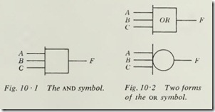
Consider the logic symbol of Fig. 10·1. This is the common form of the AND symbol. The requirement of an AND element is that all inputs must be present in order to have an output.
In the case of Fig. 10·1, inputs A and B and C must be present in order to have an output. The output is at F. It should be remembered that the loss of any one input will turn off the output.
At this point do not be concerned about what an input or an output is, or how the logic element performs its functions; just learn to read the language in symbol form.
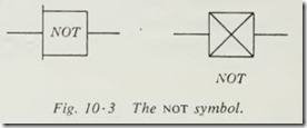
The second word in the static language is OR. The two com mon forms of the OR logic symbol are shown in Fig. 10·2. The requirement of an OR logic element is that it will have an output when any one or more of its inputs are present. The symbol of Fig. 10·2 says that there will be an output at F if input A or B or C or any combination of these inputs is present.
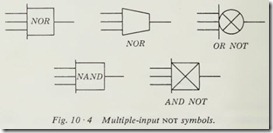
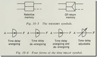
The third word in the static language is NOT or NOR. The NOT symbols are shown in Fig. 10 ·3. The requirement of a NOT is that it will produce an output when and only when its input is not present. The NOR is merely a multiple-input NOT and will have an output only when all its inputs are not present. When any one or more inputs to the NOR element are present, the output is turned off.
A third form of a negated-input logic element similar to the basic NOT or NOR is the N.\ND (Fig. 10·4) . The requirement
of a NAND is that it will have an output unless all its inputs are present. When any one or more of the inputs to the NAND element are not present , it will have an output.
The fourth word in the static language is MEMORY. Elementary symbols are shown in Fig. 10 ·5 for the basic form of MEMORY elements. The dotted line indicates the NOT output of the MEMORY. The MEMORY element remembers the condition of its output as long as the power remains on. The retentive MEMORY element remembers the state of its output even after the power is turned off. This resembles the action of a manual switch which mechanically remembers which way it was last thrown.
The off-return MEMORY remembers the state of its output until the power is turned off and then always goes to the OFF condition. This is similar to the action of the magnetic starter and a three-wire control circuit.
The fifth word in the static language is DELAY. Elementary symbols are shown in Fig. 10·6. The function of the DELAY element is to provide an output after a specific delay following the application of an input. The above function would be known
as time-delay-on-energizing . DELAY elements can be built to pro vide delay upon deenergizing as the needs of the circuit require. The symbols of Fig. 10·6 illustrate the four common forms of DELAY logic elements.
At this point it would be well to test your understanding of this new language. Consider a wall with three push buttons ·
mounted below a lamp. You walk up and press one button at a time; nothing happens. You then press the buttons in pairs; nothing happens . You then press all three buttons at once. The lamp lights. What type of logic element are the push button and lamp connected to? Of course, the logic element is an AND.
What type of logic element would necessarily have been used if the lamp came on when you pressed any one or any combina tion of buttons. Of course, it must be an OR element.
You supplied the input by pres ing the buttons, and the lamp indicated an output by turning on. The other logic elements can be as easily understood by applying the same reasoning to their specifications. If the lamp had been on and was turned off only by pressing all three buttons at once, the logic element would have been a NAND.All logic-function elements operate at very low power levels; therefore they must be followed by an amplifier in order to bring the level of power high enough to operate the device which is to be controlled. Figure 10·7 shows the symbol for an amplifier.
. It is used regardless of the physical or electrical makeup of that amplifier.
You should also be familiar with the USASI standard logic symbols, although they are not used in this book:
10 ·2 DEVELOPMENT OF LOGIC CIRCUITS
Any explanation of the control of a machine can be expressed in terms of the logic relationships of each function. Therefore, a control system breaks down into basic logic functions. The designer of conventional control circuits probably is not conscious of this, but examination of the progressive steps in designing a circuit will illustrate that the logic-function technique was actually the method used to determine the circuit design.
Consider a circuit whose requirement is that a coil M be energized when either a pressure switch PS 1 or a limit switch LSl is closed. If this circuit were developed for magnetic control, it would be as shown in Fig. 10 ·8. The logic statement of this circuit is: The coil will be energized when either PSI or LSI is closed. Therefore the logic element required would be a two input OR, as indicated in Fig. 10·9. Note the amplifier which must be inserted between the OR element and coil M to raise the power level sufficiently to energize M.
Possibly the greatest difficulty when studying static control for the first time stems from the difference in the circuits of Fig. 10·8 and Fig. 10·9. The conventional, or electromagnetic , circuit provides a means of tracing the flow of current from line 1 through the control devices through the coil back to line 2 and is easy to understand. However, the logic diagram does not indi cate the power circuit as such; rather, it is a block diagram of the control function of the circuit and at this stage may tend to leave something to be desired from the student’s point of
view. As logic circuits become more complex, the desirability of omitting the actual wiring and using symbolic representation of control functions will become more understandable. The OR element of Fig. 10·9 could be made up of vacuum tubes, satura ble reactors, or, more probably, solid-state devices such as tran sistors. The amplifier of Fig. 10·9 might well be a relay, or a vacuum-tube amplifier, or a saturable reactor, or a silicon-con trolled rectifier used in a switching mode to provide the necessary power amplification. The logic diagram does not in any way indicate the actual circuitry or components used within the logic element. This information would be found in the circuit for each element and will vary with the manufacturer involved. The student who feels it necessary to visualize a completed circuit with the logic diagram might be aided by considering that there is a common, or ground, bus which is not shown and all input and output voltages are taken from this common bus. Normal practice dictates that the common bus not be shown in order that the diagram will not be unnecessarily cluttered, since its presence adds nothing to the information given by the logic diagram.
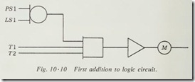
Suppose that we add to the circuit of Fig. 10 ·9 a further specification that coil M will be energized by PSI or LSI only when contacts TI and T2 are closed. Our circuit would need to be modified to that of Fig. I0 ·I 0. The logic function we
have used could be stated: The outputs of the OR and Tl and T2 must all be providing an input or ON condition before M is energized. This naturally indicates the use of a three-input AND unit, as shown in Fig.10 ·10.
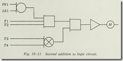
A further development of the logic circuit of Fig. 10 ·10 might include the following as the total logic statement: Coil M is to be energized when PSI or LSI and TI and T2 are closed, and only if there is no input from T3 or T4. The logic require ments assigned to T3 and T4 would indicate the use of an OR-NOT element, since the presence of an output must be accom panied by the lack of an input from T3 and T4. The circuit for our new specifications is that given in Fig. 10 ·11. The two input AND could be eliminated by using one four-input AND.
To read the diagram of Fig. 10 ·11 when no specifications are provided is relatively simple. The logic elements supply the key words to indicate the operation of the circuit. If we start at the top of the left-hand part of our circuit, the diagram will read as follows. Whenever PSI or LSI provides an input to the OR element, there will be an output. When there is an output from the OR, it provides one of the three inputs to the first AND element, which requires an input from Tl and T2 in order that it have an output. When the above conditions are met, the first AND unit provides an input to the second AND unit, which must also have an input from the OR-NOT element. The OR-NOT will have an output only when there is no input from T3 or T4. When this condition is met, both inputs are present at the second AND element, thus providing an output.
The output of the second AND element provides an input to the amplifier which supplies the power amplification necessary to energize coil M.
At this point the student may well wonder what PS 1, LSI, Tl, T2, T3, and T4 are. The details of the field wiring or sensing devices are normally found on a separate diagram and not shown on the logic diagram. These might well be contacts of pressure switches, limit switches, and thermostats. A later portion of this book will be devoted to bringing the various parts of the overall control system together in order that the student may fully un derstand the interrelationships of the sensing devices as shown on the field-wiring prints; the action part of the control circuit is represented in the logic diagram, and the power or utilization
circuit normally is shown in a third diagram.
Consider the circuit of Fig. 10·11 from an operational stand point. If PS 1 is closed but LS 1 is open, there will still be an output from the OR element. If Tl and T2 are closed, they will complete the necessary inputs to the AND element, thus providing one input to the second AND element. If T3 and T4 are open, there will be an output from the NOR element . The second AND element now has an output, and the coil is energized. Consider what would happen if T3 closed, thus providing one input to the NOR element. The result of T3 providing an input to the
NOR element is that it will lose its output. Since the second AND element now has only one input present, it no longer has an output. The amplifier has no input; therefore it has no output, and coil M is no longer energized. Consider that instead of T3 closing and providing an input to the NOR element, T2 opens and thus eliminates one input to the first AND element. The net result would be the same in both cases-coil M would not be energized.
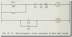
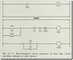
What would the circuit of Fig. 10·11 look like if it were an electromagnetic circuit and T 1, T2, T3 and T4 were thermostat contacts, and if we assumed that PSl is a pressure switch and LSI is a limit switch? The circuit is shown in Fig. I 0 ·12. This may seem to the student to be a much simpler representation of our circuit than the logic diagram of Fig. 10·11. But suppose now we add a further requirement to the circuit, that it provide complete isolation of coil M from the sensing devices and their contacts. Now the circuit becomes more complex and might possibly be wired as shown in Fig. 10·13. Neither the logic diagram nor the schematic diagram is a particularly complex circuit, but you should be able to visualize the simplicity of the logic diagram when applied to the complete automation of a machine or production line.
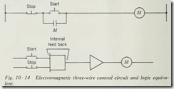
The three-wire control circuit which was used so frequently in the study of electromagnetic control circuits can be repre sented and accomplished in the logic circuit by the use of feed back. The schematic for an electromagnetic circuit and the equivalent logic diagram are shown in Fig. 10· 14. To understand the operation of the logic diagram, consider that one input is always provided to the AND element by the STOP button. When the START button is pressed, the second and final input to the AND element is provided, .and an output is produced. Once an output is produced, the internal feedback loop maintains an input even though the START button is released. This is equiva lent to the action of the maintaining contacts parallel with the START button in the electromagnetic circuit. If the STOP button is pressed, the AND element loses its output, and there is no feed back to provide an input to substitute for the START button. The circuit is now in its original off state, and even when the STOP button is returned to the closed position, the START button must be pressed before there will again be an output from the AND element.
