Domestic Lighting Circuits
There are three basic methods of wiring lights in a domestic installation.
1. Loop-in method
2. Joint Box method
3. Three Plate Ceiling Rose method
Loop-in Method
![]()
![]()
![]() The loop-in method is completed using 1.5mm2 PVC / PVC single core cables plus a Protective Conductor ( PE ). Switch feeds and switch wires are wired with brown cable. Neutrals are wired with blue cable. A protective conductor must be provided at all lighting points and at all switch positions. These must be insulated with Green / Yellow sleeving. Switches are installed at a standard height of 1.1 metres above the finished floor level ( FFL ).
The loop-in method is completed using 1.5mm2 PVC / PVC single core cables plus a Protective Conductor ( PE ). Switch feeds and switch wires are wired with brown cable. Neutrals are wired with blue cable. A protective conductor must be provided at all lighting points and at all switch positions. These must be insulated with Green / Yellow sleeving. Switches are installed at a standard height of 1.1 metres above the finished floor level ( FFL ).
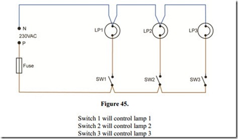
Lamps are placed in the centre of room ceilings except when more than one lamp is to be fitted. There should be no more than ten lighting points per circuit. There should be at least two lighting circuits per dwelling. This is to ensure that the entire house is not plunged into darkness if one lighting circuit fails. Figure 45 shows how three lamps, individually controlled by one- way switches are connected to the supply.
All connections are made at the switches and light fittings and are therefore easily accessible. The lamps are connected in parallel but separately switched. When all switches are in the “up” position, all lamps will be “off”.
N.B. It is extremely important to note that a fuse or MCB and the control switch must interrupt the phase conductor of the supply.
Joint Box Method
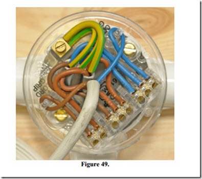
The joint box method may be completed using 1.5mm2 PVC / PVC single core cables plus a protective conductor, or 1.5mm2 Twin and Earth PVC / PVC cable.
The phase and neutral conductors are looped into the joint boxes using brown and blue cores respectively.
Neutrals and switch wires are run between joint boxes and batten lampholders / ceiling roses. Protective conductors are connected at all accessories.
Switch feeds and switch wires are run between joint boxes and switches. A twin brown cable is available for this purpose.
The running in of cables is completed simply and efficiently, but connecting up of accessories takes considerably longer than for the loop-in method.
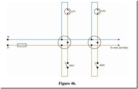
Figure 46 shows how two lamps, individually controlled by one-way switches, are connected to the supply. Protective conductors are omitted for clarity.
IMPORTANT: All neutral conductors must have blue insulation.
All live conductors, switch feeds and switch wires must have brown insulation. All protective conductors must have Green / Yellow insulation or sleeving.
This method of wiring lights is no longer used in domestic installations. It will of course be encountered in older installations for many years yet.
Note: Joint box must be fixed in position.
Three Plate Ceiling Rose Method
The three plate ceiling rose method may be completed in a similar manner to the joint box method. The three plate ceiling rose actually replaces the joint box and the batten lampholder or two plate ceiling rose. As a result there are fewer cables to be run. This involves less time at the first fixing stage.
There are more terminations to be made off and most of these are at the ceiling roses. This results in more time at the second fixing stage. All terminations will be accessible within the room.
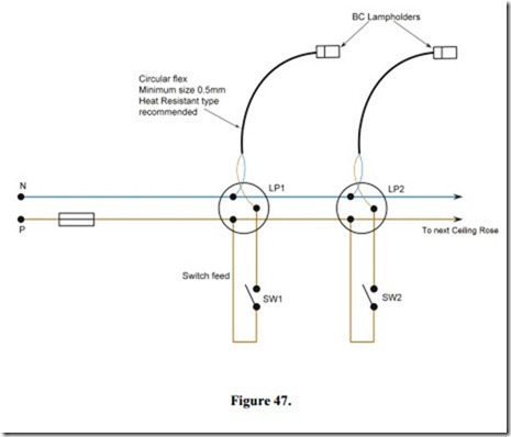
Figure 47 shows how two lamps individually controlled by one-way switches are connected to the supply. Protective conductors are omitted for clarity.
All neutral conductors must have blue insulation.
All live conductors, switch feeds and switch wires must have brown insulation. All protective conductors must have Green / Yellow sleeving.
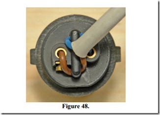
Example of Lampholder Connections
Note use of cord grip
Related posts:
Incoming search terms:
- three plate ceiling rose symbol
- joint boX method
- three plate ceiling rose method
- symbol of ceiling rose
- 3 lighting point separately controlled using 3 plate ceiling roses
- loop in method in lighting final circuits#imgrc=vqAWoPzA_G-prM:
- two lamps controlled from three different position using a 3 plate ceiling rose
- electrical symbol of three plate ceiling rose
- Domestic light point
- 3 plate ceiling rose method
- illustrate the connection of lighting circuits terminated at the joint and three plate ceiling rose
- three plate ceiling symbol
- Ceiling rose symbol
- ciruit showlng three plte celllng rose
- state accessories for lighting circuits
- purpose of ceiling rose as a lighting circuit accessories
- methods of wiring lighting circuits
- connection of lighting circuits terminated at three plate ceiling rose
- loop in method
- cwiling lose method
- joint box method in lighting final circuits
- lighting circuits and equipment
