Contactors
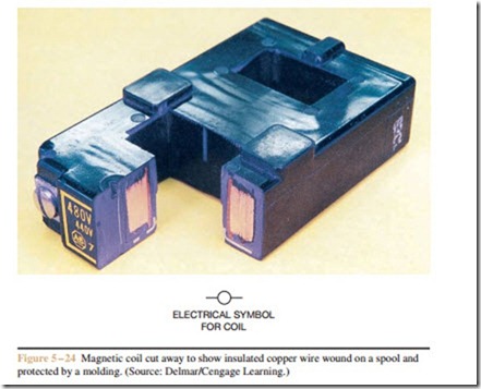
Contactors are very similar to relays in that they are electromechanical devices. Contactors can be obtained with coils designed for use on higher voltages than most relays. Most relay coils are intended to operate on voltages that range from 5 to 120 volts AC or DC. Contactors can be obtained with coils that have voltage ranges from 24 to 600 volts. Although these higher voltage coils are available, most contactors operate on voltages that generally do not exceed 120 volts for safety reasons. Contactors can be made to operate on different control circuit voltages by changing the coil. Manufacturers make coils to interchange with specific types of contactors. Most contain many turns of wire and are mounted in some type of molded case that can be replaced by disassembling the contactor (Figure 5 – 24).
It should be noted that NEMA standards require the magnetic switch device to operate properly on volt- ages that range from 85% to 110% of the rated coil voltage. Voltages can vary from one part of the country to another, and variation of voltage often occurs inside a plant as well. If coil voltage is excessive, it will draw too much current, causing the insulation to over- heat and eventually burn out. Excessive voltage also causes the armature to slam into the stationary pole pieces with a force that can cause rapid wear of the pole pieces and shorten the life of the contactor. Another effect of too much voltage is the wear caused by the movable contacts slamming into the stationary contacts, causing excessive contact bounce. Contact bounce can produce arcing, which creates more heat and more wear on the contacts.
Insufficient coil voltage can produce as much if not more damage than excessive voltage. If the coil voltage is too low, the coil will have less current flow, causing the magnetic circuit to be weaker than normal. The armature may pick up, but not completely seal against the stationary pole pieces. This can cause an air gap between the pole pieces, preventing the coil current from dropping to its sealed value. This causes excessive coil current, overheating, and coil burnout. A weak
magnetic circuit can cause the movable contacts to touch the stationary contacts and provide a connection, but not have the necessary force to permit the contact springs to provide proper contact pressure. This can cause arcing and possible welding of the contacts. Without proper contact pressure, high currents will produce excessive heat and greatly shorten the life of the contacts.
Load Contacts
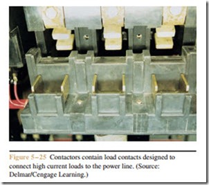
The greatest difference between relays and contac- tors is the fact that contactors are equipped with large contacts that are intended to connect high current loads to the power line (Figure 5 – 25). These large contacts are called load contacts. Depending on size, load con- tacts can be rated to control several hundred amperes. Most will contain some type of arcing chamber to help extinguish the arc that is produced when heavy current loads are disconnected from the power line. Arcing chambers can be seen in Figure 5 – 25.
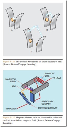
Other contacts may contain arc chutes that lengthen the path of the arc to help extinguish it. When the contacts open, the established arc will rise because of the heat produced by the arc (Figure 5 – 26). The arc is pulled farther and farther apart by the horns of the arc
chute until it can no longer sustain itself. Another device that operates according to a similar principle is the blowout coil. Blowout coils are generally used on contactors intended for use with direct current and are connected in series with the load (Figure 5 – 27). When the contact opens, the arc is attracted to the magnetic field and rises at a rapid rate. This is the same basic action that causes the armature of a direct current motor to turn.
Since the arc is actually a flow or current, a magnetic field exists around the arc. The arc’s magnetic field is at- tracted to the magnetic field produced by the blowout coil, causing the arc to move upward. The arc is extin- guished at a faster rate than is possible with an arc chute, which depends on heat to draw the arc upward. Blowout coils are sometimes used on contactors that control large amounts of alternating current, but they are most often employed with contactors that control direct current loads. Alternating current turns off each half cycle when the waveform passes through zero. This helps to extinguish arcs in alternating current circuits. Direct current,
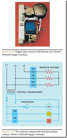
Figure 5 – 29 The contactor contains both load and auxiliary contacts. (Source: Delmar/Cengage Learning.)
however, does not turn off at periodic intervals. Once a DC arc is established, it is much more difficult to extinguish. Blowout coils are an effective means of extinguishing these arcs. A contactor with a blowout coil is shown in Figure 5 – 28.
Most contactors contain auxiliary contacts as well as load contacts. The auxiliary contacts can be used in the control circuit if required. The circuit shown in Figure 5 – 29 uses a three-pole contactor to connect a
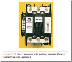
bank of three-phase heaters to the power line. Note that a normally open auxiliary contact is used to control an amber pilot light that indicates that the heaters are turned on, and a normally closed contact controls a red pilot light that indicates that the heaters are turned off. A thermostat controls the action of HR contactor coil. In the normal de-energized state, the normally closed HR auxiliary contact provides power to the red pilot light. When the thermostat contact closes, coil HR energizes and all HR contacts change position. The three load contacts close and connect the heaters to the line. The normally closed HR auxiliary contact opens and turns off the red pilot light, and the normally open HR auxiliary contact closes and turns on the amber pilot light. A size 1 contactor with auxiliary contacts is shown in Figure 5 – 30.
Vacuum Contactors
Vacuum contactors enclose their load contacts in a sealed vacuum chamber. A metal bellows connected to the movable contact permits it to move with- out breaking the seal (Figure 5 – 31). Sealing contacts inside a vacuum chamber permits them to switch higher voltages within a relatively narrow space be- tween the contacts without establishing an arc. The contacts shown in Figure 5 – 31 are rated 7.2 kilovolts and 400 amperes.
An electric arc is established when the voltage is high enough to ionize the air molecules between stationary and movable contacts. Medium voltage contactors are generally large because they must provide enough distance between the contacts to break the arc path. Some medium voltage contactors use arc sup- pressers, arc shields, and oil immersion to quench or prevent an arc. Vacuum contactors operate on the principle that if there is no air surrounding the contact, there is no ionization path for the establishment of an arc. Vacuum contactors are generally smaller in size than other types of medium voltage contactors. A three-phase vacuum contactor rated at 7.2 kilovolts and 400 amperes is shown in Figure 5 – 32. A three-phase vacuum contactor rated at 12 kilovolts and 400 amperes is shown in Figure 5 – 33.
