Induction machine rotors have either three-phase windings star-connected to three-phase slip rings or have squirrel cage type windings. The rotor threephase windings are made of full pitch coils and one or two-layers located in semiclosed or semiopen slots. Their end connections are braced against centrifugal forces. Wound rotors are typical for induction machines in the hundreds and thousands of kW ratings and more recently in a few hundreds of MW as motor/generators in pumped storage hydro power plants.
The voltage rating of rotor windings is of the same order as that in the stator of the same machine. The mmf of such windings is similar to that of stator windings treated earlier in this chapter.
By replacing the cage with an Nr/p1 phase winding (m = Nr/p1) with one conductor per slot, q = 1 and full pitch coils [17], we may use the formula for the three winding (4.44) to obtain
1
where Ib is the RMS bar current and
Kf ,bν ν = Np1s 1+ Np1r −1cos(µ ± p1) N2πr (4.53)
Let us remember that µ is a spatial harmonic and θ is a geometrical angle: θe = p1θ. Also, µ = p1 means the fundamental of mmf.
There are forward (f) and backward (b) harmonics. Only those of the order µ = KNr + p1, have Kfν = 1 while for µ = KNr – p1, they have Kbν = 1. All the other harmonics have Kfν,bν as zero. But the above harmonics are, in fact, caused by the rotor slotting. The most important, are the first ones obtained for K = 1: µfmin = Nr – p1 and µbmin = Nr + p1.
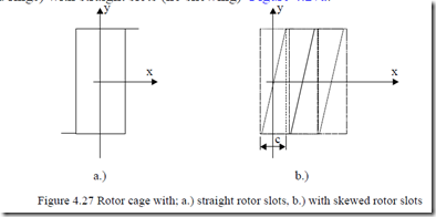
For many sub-MW-power induction machines, the rotor slots are skewed, in general by about one stator slot pitch or more, to destroy the first stator-slotcaused stator mmf harmonic (ν = Ns – p1). Again ν is a spatial harmonic; that is ν1 = p1 for the fundamental.
In this situation let us take only the case of the fundamental. The situation is as if the rotor position in (4.54) varies with y (Figure 4.27b).
for y∈[0.0, c/± 2]
Now as ω1, the stator frequency, was used in the rotor mmf, it means that
(4.54) is written in a stator reference system,
ω = ω + ω ω = Ω1 2 r ; r rp1 (4.56) with ωr as the rotor speed in electrical terms and ω2 the frequency of the currents in the rotor. The angle γ1,2 is a reference angle (at zero time) between the stator F1(θ,t) and rotor F2(θ,t) fundamental mmfs.
THE “SKEWING” MMF CONCEPT
In an induction motor on load, there are currents both in the stator and rotor.
Let us consider only the fundamentals for the sake of simplicity. With θe = πx/τ, (4.13) becomes
F1(θe,t)= F1m cos(ω1t − θe ) (4.57) with F1m from (4.14).
The resultant mmf is the sum of stator and rotor mmfs, F1(θe,t), and F2(θe,t). It is found by using (4.54) and (4.57).
Fr1(θe,t)= F1m cos(ω1t − θe )+ F2m cosω1t − θ −e πτy − π − γ( 1,2 ) (4.58)
![]()
![]() with F1m = 3W I 2K1 πp1 w1 ; F2m = πNpr1 Ib 2 (4.59) The two mmf fundamental amplitudes, F1m and F2m, are almost equal to
with F1m = 3W I 2K1 πp1 w1 ; F2m = πNpr1 Ib 2 (4.59) The two mmf fundamental amplitudes, F1m and F2m, are almost equal to
each other at standstill. In general,
F1m I
where I0 is the no load current.
For rated current, with I0 = (0.7 to 0.3)IRated, F2m/F1m is about (0.7 to 0.95) at rated load. As at start (zero speed) Is = (4.5 to 7)In, it is now obvious that in this case,
FF12mm S 1= ≈1.0 (4.61)
The angle between the two mmfs γ1,2 varies from a few degrees at standstill (S = 1) to 450 at peak (breakdown) slip SK and then goes to zero at S = 0. The angle γ1,2> 0 for motoring and γ1,2< 0 for generating. The resultant mmf Fr(θe,t), with (4.54) and
The term outside the square brackets in (4.62) is zero if there is no skewing. Consequently the term inside the square brackets is the compensated or the magnetizing mmf which tends to be small as cosπy/τ≅ 1 and thus the skewing c
= (0.5 to 2.0)τ/mq is small and the angle γ1,2∈ (π/4,−π/4) for all slip values (motoring and generating).
Therefore, we define F2skew by
F2skew ![]() F2m sin 1t e 1,2 sin (4.63) the uncompensated rotor-produced mmf, which is likely to cause large airgap flux densities varying along the stator stack length at standstill (and large slip) when the rotor currents (and F2m) are large. Thus, heavy saturation levels are expected along main flux paths in the stator and rotor core at standstill as a form of leakage flux, which strongly influences the leakage inductances as shown later in this book.
F2m sin 1t e 1,2 sin (4.63) the uncompensated rotor-produced mmf, which is likely to cause large airgap flux densities varying along the stator stack length at standstill (and large slip) when the rotor currents (and F2m) are large. Thus, heavy saturation levels are expected along main flux paths in the stator and rotor core at standstill as a form of leakage flux, which strongly influences the leakage inductances as shown later in this book.

