PULSE SYNCHRONIZATION
The triggering pulse should be applied to the controlling SCRs at the same point in each ac cycle. This is normally done by synchronizing the pulse circuit to the ac power line sup- plying the SCRs. This is done by making the power supply to the triggering circuit the same as the power supply to the SCRs.
VOLTAGE VARIATION BY AC PHASE CONTROL
SCRs and TRIACs provide a convenient method for controlling the average voltage applied to a load by changing the phase angle of the source voltage.
AC Phase Control for a DC Load Driven from an AC Source
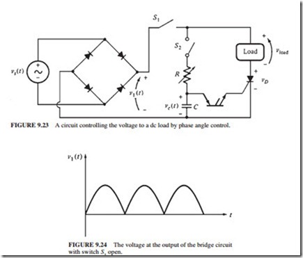
The concept of phase angle power control is illustrated in Fig. 9.23. The figure shows a voltage phase control circuit having a resistive dc load supplied by an ac source. The breakover voltage for the SCR for iG = 0 A is greater than the highest voltage in the circuit. The PNPN diode has a very low breakover voltage (around 10 V).
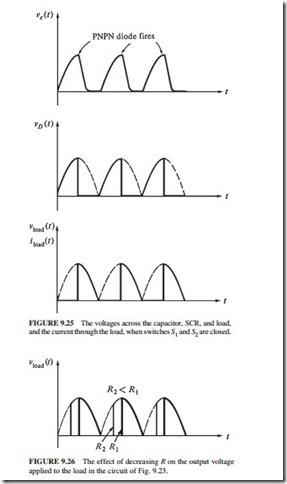
Figure 9.24 illustrates the voltage V1 at the terminals of the rectifier when switch S1 is open. If switch S1 is shut and S2 is left open, the SCR will always be off because V1 can never exceed VBO for the SCR. Since the SCR is always an open circuit, the current through it and hence the voltage on the load will be zero. When S2 is closed, the capacitor begins to charge. The capacitor continues to charge up to the breakover voltage of the PNPN diode, and the diode conducts. The current flows through the gate of the SCR, lower- ing VBO and turning on the SCR. When the SCR turns on, currents flow through it and the load. The current continues to flow after the capacitor has discharged. The SCR turns off when its current falls below the holding current IH (a few milliamperes). This occurs at the
extreme end of the half-cycle. Figure 9.25 illustrates the voltage and current waveforms for the circuit.
The power to the load can be changed by decreasing R. The capacitor will charge more quickly at the beginning of each half-cycle, and the SCR will fire soon. Since the SCR will be on for a longer period in the half-cycle, more power will be supplied to the load (Fig. 9.26). The resistor R controls the power flow to the load.
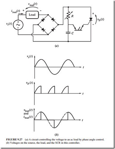
(b) Voltages on the source, the load, and the SCR in this controller.
AC Phase Control for an AC Load
An ac load can be controlled as shown in Fig. 9.27a. The load voltage and current are shown in Fig. 9.27b. A simpler ac power controller can be made by substituting the PNPN diode with a DIAC and the SCR by a TRIAC (Fig. 9.28).


