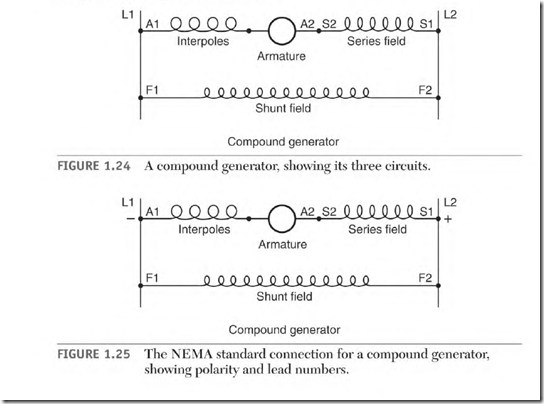
The compound generator has three circuits (Fig. 1.24), the armature and interpoles (Al and A2), the series field (Sl and S2), and the shunt field (Fl and F2).
Figure I .25 shows the NEMA standard connection for counterclockwise rotation facing the end opposite the shaft.
The Armature and Interpoles
As shown earlier, the armature leads are identified as Al and A2. The armature windings produce all of the generator’s power output. The interpoles ensure good commutation.
The Series Field
The series field (Sl and S2) has coils that either are wound over the shunt field coils or are separately formed coils. If they are wound on top of the shunt field coils, they’re separated with insulation. There is no internal connection between the series and shunt field coils. The series field coils can get hot because they are in a high-ampere circuit. They’re located on the outside of the shunt coils, where they receive maximum cooling.
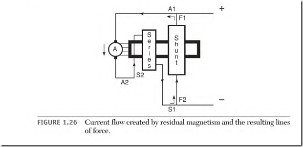
When the series field coils are separate, the coils are formed, insulated, and placed on the pole iron between the shunt field coils and the armature (Fig. 1.26).
The Shunt Field
As described earlier, the shunt field leads are identified as Fl and F2. The purpose of a generator’s shunt field is to furnish magnetic lines of force (flux) for the armature conductors to cut. As the conductors of the armature cut the lines of force, power is produced.
Operation of the Self-Excited
Compound Generator
Residual magnetism that is left in the pole iron from the previous operation creates a few lines of force. The armature conductors cut these lines of force and create an excitation voltage. The excitation voltage will cause a
small current to flow in the series and shunt fields (Fig. 1.26). This current increases the magnetic strength of the pole iron, creating more lines of force (which increase the voltage and current until full voltage output is reached). At this time, the pole iron has full magnetic saturation. This procedure can take several seconds. The shunt field furnishes nearly all the magnetism at no load.
As the load is applied, the load current produced by the armature goes through the series field, producing lines of force. These lines of force add to the shunt field’s lines of force. Instead of the iron losing magnetism (as with the shunt generator), the series field maintains full magnetic power. The results are full field strength and no drop in output voltage. The added strength of the series field stabilizes the voltage as the load is increased.
The number of turns of wire in the series field directly affects the amount of stabilizing voltage it produces. The flat-compound generator has enough turns in the series field to raise the voltage as the load is applied. When this generator reaches its full rated load, the voltage is at nameplate value.
The over-compound design will have enough turns in the series field to raise the voltage to a higher value at full load than it had at no load. (The over-compound generator’s output can be controlled downward to meet the requirement of the load.)

