Theory and Performance Criteria
A servo feed-drive system consists of four subunits:
1. The controller which has low level signals and electronics
2. The power unit which deals with high current signals
3. The load mechanism which may contain gear box to convert the high speed to low rotational speed or may have a lead screw type speed reduction mechanism to convert rotational motion to linear motion.
As was discussed in previous chapters, a mathematical model is developed for each of the subunits by employing linear or linearized relations. The load mechanism is assumed to have only load inertia and there is no speed reduction mechanism. This for reason of comparison and load mechanism depends on particular applications. In any control system employing servo motors, two important dynamic characteristics must be considered:
a. The effect of command signal which may be large displacement or small variations from the operating point. In this chapter, both small and large command displacement characteristics will be investigated.
b. The effect of external disturbance such as an external torque and friction.
In order to investigate the complete dynamic behavior, an impulse input response of the system would be an ideal test, since it excites all the modes of the system. However, because of its impracticality, this test is not normally used for the servo motor drive system. A step input can be more easily applied either as a command signal to determine the speed of response, overshoot, damping, and settling time, or as an external torque to determine the steady state and dynamic accuracy in the presence of a disturbance. In making the comparison, it is assumed that all the high performance servo motors incorporate a local velocity feedback to give improved damping and motor stiffness, that a feed-forward integrator is used to give a zero steady state error to a ramp input and that the amplifier contains a lead lag network for dynamic compensation.
In order to obtain the best performance, the parameters of the controller such as gain, time constants of the compensation network, and the gains of the feedback must be optimized to give a fast speed of response and low dynamic error caused by an external torque and input response. It was shown in previous chapters that a damping ratio of 0.6–0.7 in velocity control gives the best performance in poison control and also that this damping must be achieved at maximum value of gain in order to obtain the maximum speed of response and accuracy.
In order to facilitate the dynamic analysis and optimization of the system, the author developed a computer package to predict the stability and transient response. This was several years ago and in present day there are several commercial computer programs such as MathCad that the reader may use for particular application. The optimization procedure is as follows:
1. The gain of the system is first increased. This results in an increase in the speed of response and a reduction in the damping ratio of the system and a reduction in steady state error due to external torque.
2. In order to compensate the reduction in damping, a lead-lag network is introduced. The usual effect of the lag network is to introduce damping in the fundamental mode of the system but has the opposite effect on the higher mode. The effect of the lead network is to increase the damping in the higher mode of vibration.
3. The improvement achieved by a lead-lag network alone is limited, since at high gain the contribution of higher modes of vibration of the systems becomes significant. Acceleration feedback together with a lead-lag network, improves the dynamic performance of the system by not only introducing damping in the
higher modes of vibration but also preventing their contribution being dominant in the response. Motor current is used as a quasi-acceleration feedback by most manufactures, and by increasing the gain of the current feedback, a more effective compensation and damping may be achieved. If this is adopted, practical limitations such as current limit and the speed of the current rise must be considered in the optimization.
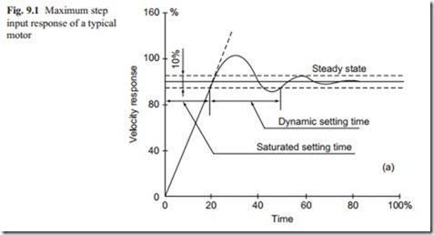
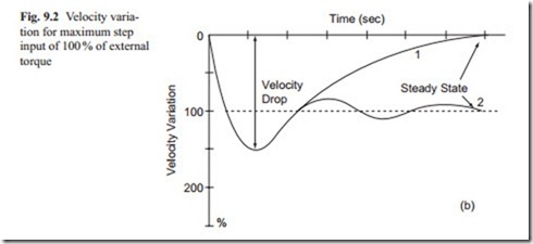
Having optimized the performance, a typical response of the system to step input of velocity is shown in Fig. 9.1 and the velocity change for maximum step input of external torque is shown in Fig. 9.2.
The time of response, defined as the total time to when the output reaches 95 % of its final value as shown in Fig. 9.1 may be divided into saturated response and dynamic settling time as will be described in the next sections. The dynamic settling time is obtainable from mathematical modeling which is only valid for a small variation of input signal. The saturated time response depends on maximum or rated torque of the motor and the total inertia of the system referred to the motor shaft. If the maximum torque and total inertia are constant, the first part of Fig. 9.1 is a straight line.
The effect of an external torque may be represented as the maximum velocity drop from the steady state as shown in Fig. 9.2. The velocity variation due to the external torque eventually becomes zero due to the feed-forward integrator in the system. The results of the analysis were substantiated by some experimental tests several years ago and will not be included in this book. It should be noted that in both Figs. 9.1 and 9.2, the typical response is presented in terms of percentage of the rated velocity and external torque. The actual response for each motor will have numerical values and this will be used in the next sections.

