MAGNETIC CIRCUITS
So far we have assumed that the source of the magnetic Weld is a permanent magnet. This is a convenient starting point as all of us are familiar with magnets, even if only of the fridge-door variety. But in the majority of motors, the working magnetic Weld is produced by coils of wire carrying current, so it is appropriate that we spend some time looking at how we arrange the coils and their associated iron ‘magnetic circuit’ so as to produce high magnetic Welds which then interact with other current-carrying conductors to produce force, and hence rotation.
First, we look at the simplest possible case of the magnetic Weld surrounding an isolated long straight wire carrying a steady current (Figure 1.4). (In the Wgure, the þ sign indicates that current is Xowing into the paper, while a dot is used to signify current out of the paper: these symbols can perhaps be remembered by picturing an arrow or dart, with the cross being the rear view of the Xetch, and the dot being the approaching point.) The Xux lines form circles concentric with the wire, the Weld strength being greatest close to the wire. As might be expected, the Weld strength at any point is directly proportional to the current. The convention for determining the direction of the Weld is that the positive direction is taken to be the direction that a right-handed corkscrew must be rotated to move in the direction of the current.
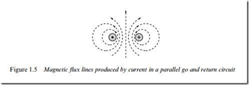
Figure 1.4 is somewhat artiWcial as current can only Xow in a complete circuit, so there must always be a return path. If we imagine a parallel ‘go’ and ‘return’ circuit, for example, the Weld can be obtained by superimposing the Weld produced by the positive current in the go side with the Weld produced by the negative current in the return side, as shown in Figure 1.5.
We note how the Weld is increased in the region between the conductors, and reduced in the regions outside. Although Figure 1.5 strictly only applies to an inWnitely long pair of straight conductors, it will probably not come as a surprise to learn that the Weld produced by a single turn of wire of rectangular, square or round form is very much the same as that shown in Figure 1.5. This enables us to build up a picture of the Weld
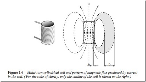
that would be produced in air, by the sort of coils used in motors, which typically have many turns, as shown for example in Figure 1.6.
The coil itself is shown on the left in Figure 1.6 while the Xux pattern produced is shown on the right. Each turn in the coil produces a Weld pattern, and when all the individual Weld components are superimposed we see that the Weld inside the coil is substantially increased and that the closed Xux paths closely resemble those of the bar magnet we looked at earlier. The air surrounding the sources of the Weld oVers a homoge- neous path for the Xux, so once the tubes of Xux escape from the concentrating inXuence of the source, they are free to spread out into the whole of the surrounding space. Recalling that between each pair of Xux lines there is an equal amount of Xux, we see that because the Xux lines spread out as they leave the conWnes of the coil, the Xux density is much lower outside than inside: for example, if the distance ‘b’ is say four times ‘a’ the Xux density Bb is a quarter of Ba.
Although the Xux density inside the coil is higher than outside, we would Wnd that the Xux densities which we could achieve are still too low to be of use in a motor. What is needed Wrstly is a way of increasing the Xux density, and secondly a means for concentrating the Xux and pre- venting it from spreading out into the surrounding space.
Magnetomotive force (MMF)
One obvious way to increase the Xux density is to increase the current in the coil, or to add more turns. We Wnd that if we double the current, or the number of turns, we double the total Xux, thereby doubling the Xux density everywhere.
We quantify the ability of the coil to produce Xux in terms of its magnetomotive force (MMF). The MMF of the coil is simply the product of the number of turns (N) and the current (I), and is thus expressed in ampere-turns. A given MMF can be obtained with a large number of turns of thin wire carrying a low current, or a few turns of thick wire carrying a high current: as long as the product NI is constant, the MMF is the same.
Electric circuit analogy
We have seen that the magnetic Xux which is set up is proportional to the MMF driving it. This points to a parallel with the electric circuit, where the current (amps) that Xows is proportional to the EMF (volts) driving it.
In the electric circuit, current and EMF are related by Ohm’s Law, which is
For a given source EMF (volts), the current depends on the resistance of the circuit, so to obtain more current, the resistance of the circuit has to be reduced.
We can make use of an equivalent ‘magnetic Ohm’s law’ by introducing the idea of reluctance (R). The reluctance gives a measure of how diYcult it is for the magnetic Xux to complete its circuit, in the same way that resistance indicates how much opposition the current encounters in the electric circuit. The magnetic Ohm’s law is then
We see from equation 1.4 that to increase the Xux for a given MMF, we need to reduce the reluctance of the magnetic circuit. In the case of the example (Figure 1.6), this means we must replace as much as possible of the air path (which is a ‘poor’ magnetic material, and therefore constitutes a high reluctance) with a ‘good’ magnetic material, thereby reducing the reluctance and resulting in a higher Xux for a given MMF.
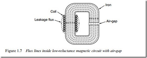
The material which we choose is good quality magnetic steel, which for historical reasons is usually referred to as ‘iron’. This brings several very dramatic and desirable beneWts, as shown in Figure 1.7.
Firstly, the reluctance of the iron paths is very much less than the air paths which they have replaced, so the total Xux produced for a given MMF is very much greater. (Strictly speaking therefore, if the MMFs and cross-sections of the coils in Figures 1.6 and 1.7 are the same, many more Xux lines should be shown in Figure 1.7 than in Figure 1.6, but for the sake of clarity similar numbers are indicated.) Secondly, almost all the Xux is conWned within the iron, rather than spreading out into the surrounding air. We can therefore shape the iron parts of the magnetic circuit as shown in Figure 1.7 in order to guide the Xux to wherever it is needed. And Wnally, we see that inside the iron, the Xux density remains uniform over the whole cross-section, there being so little reluctance that there is no noticeable tendency for the Xux to crowd to one side or another.
Before moving on to the matter of the air-gap, we should note that a question which is often asked is whether it is important for the coils to be wound tightly onto the magnetic circuit, and whether, if there is a multi-layer winding, the outer turns are as eVective as the inner ones. The answer, happily, is that the total MMF is determined solely by the number of turns and the current, and therefore every complete turn makes the same contribution to the total MMF, regardless of whether it happens to be tightly or loosely wound. Of course it does make sense for the coils to be wound as tightly as is practicable, since this not only minimises the resistance of the coil (and thereby reduces the heat loss) but also makes it easier for the heat generated to be conducted away to the frame of the machine.
The air-gap
In motors, we intend to use the high Xux density to develop force on current-carrying conductors. We have now seen how to create a high Xux density inside the iron parts of a magnetic circuit, but, of course, it is physically impossible to put current-carrying conductors inside the iron. We therefore arrange for an air-gap in the magnetic circuit, as shown in Figure 1.7. We will see shortly that the conductors on which the force is to be produced will be placed in this air-gap region.
If the air-gap is relatively small, as in motors, we Wnd that the Xux jumps across the air-gap as shown in Figure 1.7, with very little tendency to balloon out into the surrounding air. With most of the Xux lines going straight across the air-gap, the Xux density in the gap region has the same high value as it does inside the iron.
In the majority of magnetic circuits consisting of iron parts and one or more air-gaps, the reluctance of the iron parts is very much less than the reluctance of the gaps. At Wrst sight this can seem surprising, since the distance across the gap is so much less than the rest of the path through the iron. The fact that the air-gap dominates the reluctance is simply a reXection of how poor air is as a magnetic medium, compared to iron. To put the comparison in perspective, if we calculate the reluctances of two paths of equal length and cross-sectional area, one being in iron and the other in air, the reluctance of the air path will typically be 1000 times greater than the reluctance of the iron path. (The calculation of reluc- tance will be discussed in Section 1.3.4.)
Returning to the analogy with the electric circuit, the role of the iron parts of the magnetic circuit can be likened to that of the copper wires in the electric circuit. Both oVer little opposition to Xow (so that a negligible fraction of the driving force (MMF or EMF) is wasted in conveying the Xow to where it is usefully exploited) and both can be shaped to guide the Xow to its destination. There is one important diVerence, however. In the electric circuit, no current will Xow until the circuit is completed, after which all the current is conWned inside the wires. With an iron magnetic circuit, some Xux can Xow (in the surrounding air) even before the iron is installed. And although most of the Xux will subsequently take the easy route through the iron, some will still leak into the air, as shown in Figure 1.7. We will not pursue leakage Xux here, though it is sometimes important, as will be seen later.
Reluctance and air-gap flux densities
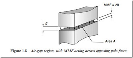
If we neglect the reluctance of the iron parts of a magnetic circuit, it is easy to estimate the Xux density in the air-gap. Since the iron parts are then in eVect ‘perfect conductors’ of Xux, none of the source MMF (NI ) is used in driving the Xux through the iron parts, and all of it is available to push the Xux across the air-gap. The situation depicted in Figure 1.7
therefore reduces to that shown in Figure 1.8, where an MMF of NI is applied directly across an air-gap of length g.
To determine how much Xux will cross the gap, we need to know its reluctance. As might be expected, the reluctance of any part of the mag- netic circuit depends on its dimensions, and on its magnetic properties, and the reluctance of a rectangular ‘prism’ of air, of cross-sectional area A and length g as in Figure 1.8 is given by
where m0 is the so-called ‘primary magnetic constant’ or ‘permeability of free space’. Strictly, as its name implies, m0 quantiWes the magnetic properties of a vacuum, but for all engineering purposes the permeability of air is also m0. The value of the primary magnetic constant (mo) in the SI system is 47 x 10-7 H/m; rather surprisingly, there is no name for the unit of reluctance.
In passing, we should note that if we want to include the reluctance of the iron part of the magnetic circuit in our calculation, its reluctance would be given by
and we would have to add this to the reluctance of the air-gap to obtain the total reluctance. However, because the permeability of iron (mfe) is so much higher than fl0, the iron reluctance will be very much less than the gap reluctance, despite the path length l being considerably longer than the path length (g) in the air.
Equation 1.5 reveals the expected result that doubling the air-gap would double the reluctance (because the Xux has twice as far to go), while doubling the area would halve the reluctance (because the Xux has two equally appealing paths in parallel). To calculate the Xux, F, we use the magnetic Ohm’s law (equation 1.4), which gives
Equation 1.7 is delightfully simple, and from it we can calculate the air- gap Xux density once we know the MMF of the coil (NI) and the length of the gap (g). We do not need to know the details of the coil-winding as long as we know the product of the turns and the current, nor do we need to know the cross-sectional area of the magnetic circuit in order to obtain the Xux density (though we do if we want to know the total Xux, see equation 1.6).
For example, suppose the magnetising coil has 250 turns, the current is 2 A, and the gap is 1 mm. The Xux density is then given by
(We could of course obtain the same result using an exciting coil of 50 turns carrying a current of 10 A, or any other combination of turns and current giving an MMF of 500 ampere-turns.)
If the cross-sectional area of the iron was constant at all points, the Xux density would be 0.63 T everywhere. Sometimes, as has already been mentioned, the cross-section of the iron reduces at points away from the air-gap, as shown for example in Figure 1.3. Because the Xux is com- pressed in the narrower sections, the Xux density is higher, and in Figure 1.3 if the Xux density at the air-gap and in the adjacent pole-faces is once again taken to be 0.63 T, then at the section aa’ (where the area is only half that at the air-gap) the Xux density will be 2 x 0:63 ¼ 1:26 T.
Saturation
It would be reasonable to ask whether there is any limit to the Xux density at which the iron can be operated. We can anticipate that there must be a limit, or else it would be possible to squash the Xux into a
vanishingly small cross-section, which we know from experience is not the case. In fact there is a limit, though not a very sharply deWned one.
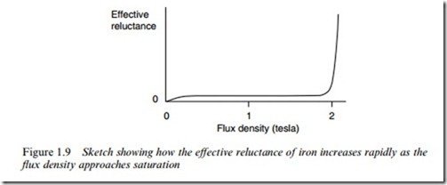
Earlier we noted that the iron has almost no reluctance, at least not in comparison with air. Unfortunately this happy state of aVairs is only true as long as the Xux density remains below about 1.6 – 1.8 T, depending on the particular steel in question. If we try to work the iron at higher Xux densities, it begins to exhibit signiWcant reluctance, and no longer behaves like an ideal conductor of Xux. At these higher Xux densities, a signiWcant proportion of the source MMF is used in driving the Xux through the iron. This situation is obviously undesirable, since less MMF remains to drive the Xux across the air-gap. So just as we would not recommend the use of high-resistance supply leads to the load in an electric circuit, we must avoid overloading the iron parts of the magnetic circuit.
The emergence of signiWcant reluctance as the Xux density is raised is illustrated qualitatively in Figure 1.9.
When the reluctance begins to be appreciable, the iron is said to be beginning to ‘saturate’. The term is apt, because if we continue increas- ing the MMF, or reducing the area of the iron, we will eventually reach an almost constant Xux density, typically around 2 T. To avoid the undesirable eVects of saturation, the size of the iron parts of the mag- netic circuit are usually chosen so that the Xux density does not exceed about 1.5 T. At this level of Xux density, the reluctance of the iron parts will be small in comparison with the air-gap.
Magnetic circuits in motors
The reader may be wondering why so much attention has been focused on the gapped C-core magnetic circuit, when it appears to bear little
resemblance to the magnetic circuits found in motors. We will now see that it is actually a short step from the C-core to a magnetic motor circuit, and that no fundamentally new ideas are involved.
The evolution from C-core to motor geometry is shown in Figure , which should be largely self-explanatory, and relates to the Weld system of a d.c. motor.
We note that the Wrst stage of evolution (Figure 1.10, left) results in the original single gap of length g being split into two gaps of length g/2, reXecting the requirement for the rotor to be able to turn. At the same time the single magnetising coil is split into two to preserve symmetry. (Relocating the magnetising coil at a diVerent position around the magnetic circuit is of course in order, just as a battery can be placed anywhere in an electric circuit.) Next, (Figure 1.10, centre) the single magnetic path is split into two parallel paths of half the original cross- section, each of which carries half of the Xux: and Wnally (Figure 1.10, right), the Xux paths and pole-faces are curved to match the rotor. The coil now has several layers in order to Wt the available space, but as discussed earlier this has no adverse eVect on the MMF. The air-gap is still small, so the Xux crosses radially to the rotor.

