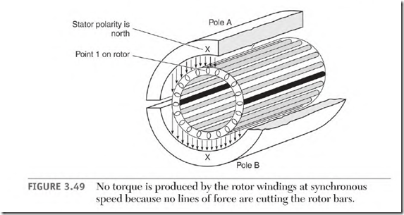
When there is no load, a squirrel cage rotor will accelerate to nearsynchronous speed. The rotor Hz are 0, with no torque at synchronous speed. Figure 3.49 illustrates why.
Stator pole A (in Fig. 3.49) is north and point I on the rotor is aligned with it. By the time point 1 of the rotor aligns with pole B of the stator, the polarity of pole B has changed to north. (This compares to the rotor being stationary in a DC magnetic field.)
At synchronous speed, no lines of force cut the rotor bars and no power is transformed into them. When no current flows in the rotor bars, there is no torque.
If the rotor was to somehow accelerate faster than synchronous speed, it would generate power instead of producing torque. The rotor iron is magnetized, and its flux cuts the stator coils, producing power.
Rotor Bar Stress
The squirrel cage winding of the rotor has a wide range of amperes. Rotor amperes are very high every time the motor starts. This causes the rotor bars to get hot. The expansion rate of the rotor bars is much greater than that of the iron. The resulting stress can break the rotor bars.
There are many magnetic polarity changes in the rotor iron from the time a motor starts until it reaches loaded speed. This creates constant vibration in the rotor bars. As a rotor bar crosses each stator slot and aligns with the iron of the next stator tooth, there’s a different magnetic pull.
Rotor bars are skewed to reduce the slot- and tooth-caused vibration. They will crack or break if they aren’t tight in the slot.
Cast aluminum squirrel cage windings are used in most standard induction motors. Casting the aluminum rotor bars and end rings results in a tight fit.
This reduces the chance of bars getting loose and cracking from vibration.
Aluminum bars and end rings must be grossly oversized to prevent the normally high starting current from melting them. Oversized bars reduce the amount of magnetic path of the rotor. This is why rotors with cast aluminum windings are larger than rotors with windings made of copper or other alloys.
Broken Rotor Bars
Broken rotor bars decrease a motor’s power. Current flowing in each bar contributes to the motor’s torque. The current flow is all but stopped when a bar is cracked or broken. The cracked bar is embedded in iron but because the voltage is so low, very little current is carried by the iron.
The tip of a solder gun is a good example of low voltage and high current. When the solder gun has had a lot of use, the tip doesn’t get hot when the gun is turned on. Even if the nuts holding the tip seem very tight, tightening them slightly makes it work as it should. (Very low resistance virtually stops current flow when voltage is this low.)
The number of broken rotor bars and the load determine whether or not the motor fails. The motor’s amperes are much lower than normal (with no load). (Amperes in the stator winding depend on the power demand of the rotor winding.) A maximum-loaded motor with broken rotor bars will soon fail. The stator windings will look charred—as though they failed—from being overloaded.
Cracked End Rings
Cracked end rings cause uneven torque and decrease the motor’s power, resulting in failure. The failed winding—as with open rotor bars—will be charred as though the motor failed from being overloaded.
The size of the end rings is determined by the number of rotor bars a stator pole covers. End rings must be larger than the circular mil area of half of the rotor bars that are covered by the pole.
Aluminum end rings sometimes have a bubble or piece of slag embedded in them. Any type of flaw will reduce the circular mil area at this point. A reduction in circular mils restricts current flow and the spot gets hot.
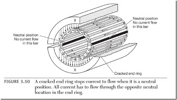
High starting current will melt the aluminum at this spot, opening the end ring. When an open aligns with a neutral spot (between the stator poles),
the entire rotor current is forced to flow, as shown in Fig. 3.50. The current then doubles in the part of the ring located in the adjacent neutral spot. High current will soon melt the end ring in this area, creating another open.
Misaligned Rotor Iron
When the rotor iron is misaligned with the stator iron, the size of the motor’s magnetic path is decreased. The result is loss of torque and
increased magnetizing amperes. The increased magnetizing amperes overheat the motor (even with no load).
Like a motor with broken rotor bars, a fully loaded motor soon fails. The windings will look charred—as with a motor that has failed from an overload.
Other than noticing high no-load amperes, the only way to identify this problem is to view it. It may be necessary to remove one end frame to see the misalignment.

