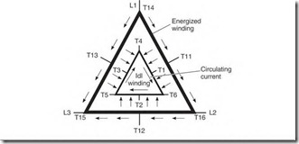
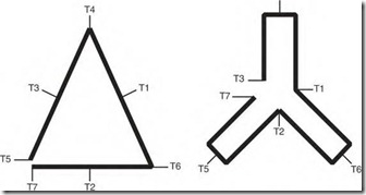
Some motors with three or more speeds require their two-speed winding(s) to be open when not in use. As seen in Fig. 7.4, a circulating current is transformed into the idle winding from the energized winding. The power used by the circulating current increases the amperes of the energized winding and quickly overheats it. To prevent circulating current, the idle winding is opened, as shown in Figs. 7.5a and 7.5b. The lead T7 or T 17 is the end of the opened phase. (Lead T17 is connected to the higher-speed winding.) The motor’s control joins T7 (or T17) with its respective lead when
FIGURE 7.4 Schematic of a constant-horsepower winding that is sharing the stator with another winding. A circulating current will occur if the idle winding isn’t opened.
(a) (b)
FIGURE 7.5 (a) Schematic for a constant-horsepower motor and (b) for a constant-torque motor, connected so they won’t have circulating current.
the winding is energized. Lead T7 (or Tl 7) is joined with T3 in the constanttorque motor and with T5 in the constant-horsepower motor.
Some three-speed motors have a two-speed winding and a one-speed winding sharing the slots. The single-speed winding will have a special internal connection that doesn’t require the idle two-speed winding to be opened. If this motor isn’t connected as it was originally connected, the single-speed winding will get hot (because of circulating current in the twospeed winding).
Circulating current occurs because the poles of one winding align with the poles of another winding. A proper connection will allow another pole (in its circuit) to cancel the circulating current created by an aligned pole.
A winding needs half as many circuits as it has poles, to prevent circulating current without opening it. Each internal circuit must contain two poles that are located on opposite sides of the stator. Spacing two poles of the circuit across from each other keeps them out of magnetic alignment with the poles of another winding (which has a different number of poles). This arrangement cancels current that would circulate because of the closed loop. If both windings are connected single-circuit wye, this spacing isn’t necessary.
Rotor Problems in the Multispeed Motor
The multispeed motor has a squirrel cage rotor like any induction motor. It is more likely to have bars made with copper, brass, or a similar alloy. These alloys have more problems than aluminum. Rotor problems include open rotor bars, open end rings, and other problems described under “Function of the Squirrel Cage Rotor” in Chapter 3 (see Fig. 3.48).
Open rotor bars and end rings decrease the motor’s power, as described earlier. If a motor takes longer to start, or runs hotter (and more slowly) than it should, the rotor may have a problem. (Low supply voltage will also cause this problem.)
Open rotor bars can be detected with a (correct size) ohmmeter attached to any two winding leads of the same winding. Thrn the shaft; note the high and low readings. Departures from normal readings indicate an open rotor bar.
Rotors can be rebuilt to original specifications. They can be rebarred if made of copper or other alloy, or recast if made of aluminum. Multispeed motors are costly and hard to replace, making it cost effective to rebuild their rotors. Rotors of large motors are routinely rebuilt (Fig. 7.6).
FIGURE 7.6 A rotor being completely rebuilt. Jasper Electric.


![clip_image002[5] clip_image002[5]](http://machineryequipmentonline.com/electric-equipment/wp-content/uploads/2017/05/clip_image0025_thumb.jpg)