Components of the squirrel cage rotor are rotor bars, end rings, and laminated iron.
The bars and end rings of the squirrel cage rotor are illustrated in Fig. 3.44. The bars (located in the slots of the rotor iron) are all connected together by end rings. Rotor bars are made in many shapes and sizes, as shown in Fig. 3.45.
End rings join all the rotor bars. The size of the end rings depends on the number of bars covered by the face of one pole. Their size must be slightly larger than the total circular mil area of one-half the bars, covered by the face
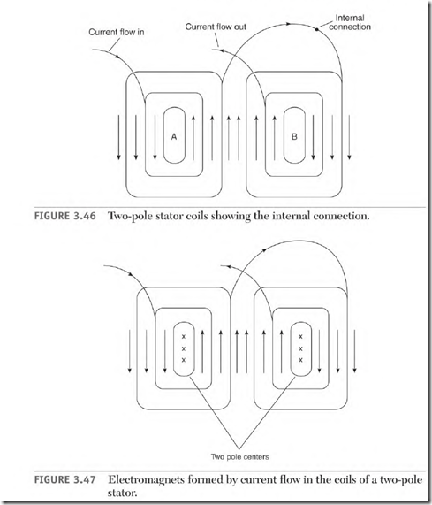
at points A and B. The center coils of the stator poles (Fig. 3.47) will straddle at least two slots. Current flow in the center coil of the poles is in opposite directions on both sides of the straddled slots. (This creates a pole center like that of a DC shunt field pole.)
Current flow in the outer coils of each stator pole is in the same direction. Because the current flows in the same direction, the outer coils may be located in adjacent slots, or they may share the same slot.
All stator coils are well insulated (from the slot iron). The thickness of the insulation is determined by the operating voltage value.
Function of the Squirrel Cage Rotor
The voltage transformed into the bars of the squirrel cage winding from the stator coils is very low. Rotor bars don’t have to be insulated from the iron— unlike stator coils—because the voltage transformed into them is so low. The turn ratio of the stator winding and the squirrel cage winding steps the voltage down to less than I volt (similar to the solder gun).
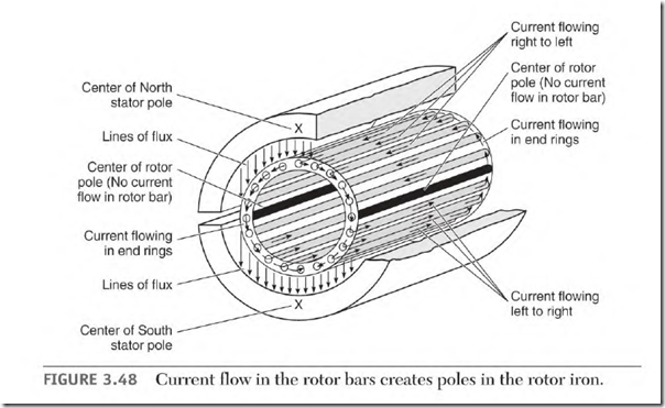
Current flow in the rotor bars creates poles that are the same shape as the stator poles (coil groups). Figure 3.48 shows the current flow in the bars of a squirrel cage rotor at loaded speed.
Stator pole groups are connected so that their polarity is opposite the one next to it. This polarity sequence becomes the same in the rotor. The rotor bars will each have a different amount of power transformed into them. The amount of power is related to the position of the bars in reference to the stator poles.
The bars located at the center (90 0 ) of the stator poles are cut by the most lines of force; therefore, they create the most power. Bars located away from center (90 0 ) create progressively less power. When a bar’s angle to the pole face is less than 90 electrical degrees, fewer lines of force cut it. Bars located in the neutral area don’t create any power. No lines of force are cutting them at this position. (The iron around the idle bars becomes the rotor’s pole centers.)
The opposite polarity stator pole transforms power of the opposite polarity into the bars located within its pole face. Current flows through the end rings from bars of one polarity to bars of the opposite polarity. Thro poles form in the rotor iron (which is centered in the neutral area of the stator poles). A repel and attract magnetic force is established between the stator and rotor windings. This magnetic interaction creates torque that pulls the load.
Rotor Hertz and Amperes
The induction motor is very comparable to a transformer. The primary amperes of a transformer are determined by the load applied to the secondary. If the secondary winding were shorted, the primary winding would overheat and be destroyed.
In an induction motor, the rotor bars (secondary winding) are shorted together by end rings. At 0 RPM (locked rotor) the rotating magnetic field of the stator is at synchronous speed. The magnetic lines of force are cutting the rotor bars at maximum Hz (cycles per second). This transforms a very high AC current into the rotor bars. (The stator is furnishing this power, so the amperes are also very high in the stator.) As the rotor accelerates, the difference between the synchronous speed of the stator’s rotating magnetic field and the speed of the rotor decreases. Rotor Hz become lower as rotor speed increases. As rotor I-IZ go down, fewer lines of force cut its rotor bars, resulting in fewer amperes in both the rotor and stator. With rated load applied, the rotor speed will be nameplate RPM, and stator amperes will be at nameplate value. At loaded speed, rotor Hz are about 1.5 to 3 cycles per second. The amperes are high enough in the rotor winding (at this RPM) to produce the motor’s rated torque.
Slip, Hertz, and Motor Speed
The difference between synchronous speed and nameplate speed is called slip. Slip produces a calculated number of amperes, torque, and horsepower that equal the motor’s rating. A motor rated continuous duty won’t overheat at rated RPM.
The following calculations start with the basics and explain the relationship of poles, power supply Hz, synchronous speed, slip, and rotor
One pole — 180 electrical degrees.
Thro poles = 360 0 (the number of degrees in one cycle).
One Hz of power is produced when a magnet passes one pair of poles in I second. Sixty Hz = 60 pairs of poles passed in 1 second. FIZ x 60 seconds = pairs of poles passed in 1 minute.
60 Hz x 60 seconds = 3600 pairs of poles passed in 1 minute.
3600 + number of pairs of poles = synchronous RPM @ 60 Hz.
3600 x 2 = 7200 (the total number of poles passed in one minute).
7200 + number of poles = synchronous RPM @ 60 Hz.
7200 + synchronous RPM = number of poles in a 60-Hz motor.
Any Hz x 60 seconds (to get cycles per minute) x 2 = numerator.
Numerator + poles = synchronous RPM.
Numerator + synchronous RPM = poles.
Slip = the difference between synchronous speed and loaded speed. 1800 – 1750 (nameplate RPM) = 50 RPM of slip.
50 – 1800 x 100 = 2.7% slip.
I-IZ x % of slip = rotor Hz.
60 x 2.7% = 1.66 rotor Hz.
Synchronous speed of a four-pole motor on 60 Hz is 1800 RPM. High-slip rotors have 5 percent slip or 3 rotor Hz. Synchronous motors have no slip. Their poles will be misaligned a few degrees (behind the stator poles). The amount of misalignment is determined by the load and the strength of the rotating field.

