Stator and Coil Winding
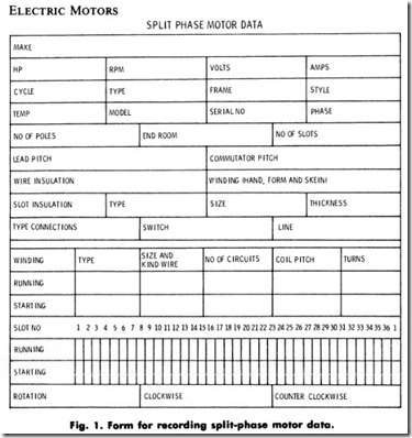
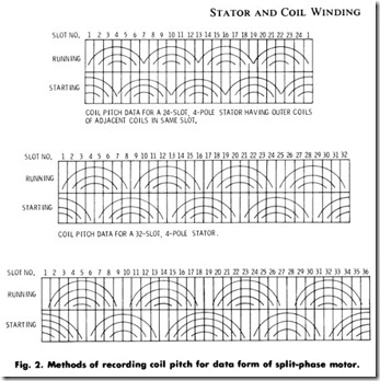
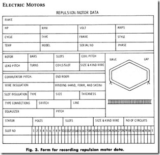
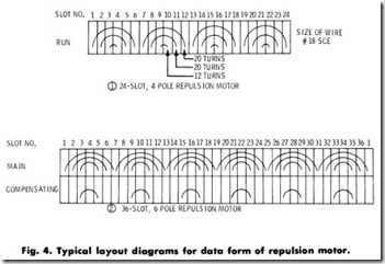
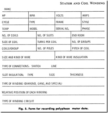
Recording data is one of the most important steps in rewinding a stator or coil. It consists of noticing certain specific information concerning the old winding so that no difficulty will be encountered when the stator or coil is rewound. As much information as possible is recorded before stripping, and the remainder is recorded during the stripping operation. Another important item is the distance the coils protrude from the stator. This is called end room. It is important that the new coils do not extend beyond the slots any further than this distance. If they do, the end bells may press against the coils causing a short circuit, or the end bells may not be able to be replaced at all. A form for recording data for a split-phase motor is shown in Fig. 1, and methods of recording the coil pitch data on the form are shown in Fig. 2. A form for recording data for a repulsion motor is shown in Fig. 3, and typical layout diagrams for recording the data on this form are shown in Fig. 4. A form for recording data for a polyphase motor is shown in Fig. 5. The informa tion Iisted above must be recorded in such a manner as to enable any electric motor repairman to rewind the motor or generator.
DATA-TAKING WHILE STRIPPING
The importance of observing and recording data during the stripping procedure is not to be minimized. The following methods and pro cedures will aid in observing and recording the important details after all preliminary data have been recorded.
Split-Phase Stators
Sometimes it is only necessary to replace the starting winding. If care is exercised when removing the starting winding, the rest of the stator will not need a rewind job. Single-phase motors with more than four poles are a rarity, but if a motor with six or eight poles is encountered, be certain to record the number of poles for the starting winding (before stripping), since they will differ in many instances from that of the running winding. Follow the procedures outlined below for both start ing and running windings.
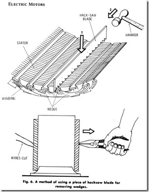
1. Remove all wedges. Use a wedge remover or piece of hacksaw blade with the toothset ground off, Fig. 6.
2. Cut through the end turns of the windings of one pole on one side.
Count and record the number of wires entering the slots for every coil side of one side of a pole. The location of running-winding
pole core slots, with respect to the frame, is to be recorded by punch-marking the center slot or slots of each pole. In many single-phase stator cores, the center of each main pole is iden tified by a change in slot size. This is sufficient for properly locating the poles when rewinding.
Strip the stator by using a pair of long nose pliers on the side of 1. the stator on which the pole windings are not cut, Fig. 6. If it is difficult to remove the windings, the procedures for application of heat or caustic soda solution should be followed. Also, the windings may be connected across full-line current. This causes them to overheat and burn away varnishes and insulations, there by becoming loosened.
Repulsion Type Stators
Follow the same procedure as for split-phase stators described above.
Polyphase Stators
It is important, before stripping a polyphase stator, to examine and record the winding circuits for the particular unit which is being rewound. The use of the connection diagrams found in the appendix, is an aid in this respect. After the stator winding circuits and preliminary data have been recorded, the electric motor repairman can proceed to strip the stator according to the procedure outlined for Split-Phase Motors. A form for recording polyphase motor data is shown in Fig. 5.
REWINDING PROCEDURE
The procedure for insulating the slots is similar to that used for armatures. It may be necessary to cut and fit 1I 16 inch ( 1 .6 mm) fiber for the core ends and the procedure outlines in Insulating the Core Ends and Shaft, located in Chapter 15. Use the procedures in the same location steps number 1 and 3 through 6. The stator is supported on a bench block, its own stand, or armature stand fitted with stator adaptors.
COIL FORMING
Most single-phase stators are hand-wound. In very few instances a single-phase stator may be found which is composed of preformed coils and then, in the majority of cases, they are placed, as discussed under Polyphase Stators. The various methods used for rewinding single phase stators are listed below.
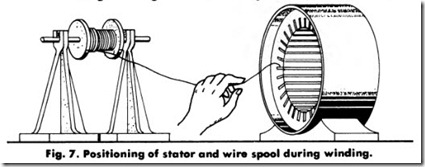
1. Hand winding. Hand winding may be used for both the starting and running windings. In this method, the wires are placed in the slots, one turn at a time, until the winding operation is completed, Fig. 7. With the stator still supported after completing the insulating, proceed as follows:
a. Set up the reel of proper size wire for the stator on a reel rack with a suitable tensioning device.
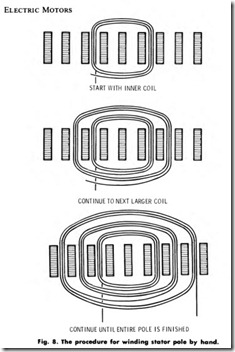
b. Insert the wire into a slot for the start of an inner coil, Fig. 8.
c. Wind into the slot of proper coil pitch for the inner winding according to the recorded data.
d. Continue to the next larger coil.
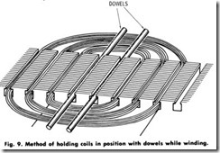
e. Continue to the next larger coil until the entire pole is finished. Wooden dowels may be placed in empty slots to hold coils in position while winding, Fig. 9.
f. Cut the wire and wedge the winding permanently in place if it is a top winding.
g. If it is a bottom winding, push temporary, loose-fitting wooden or fiber wedges in place for each slot until the stator is completed.
h. Remove the dowels.
i. Continue b and h, above, for every pole until the bottom winding of the stator is wound or, if a top winding, the stator is wound completely.
j. Set up a reel of proper size wire for the starting winding.
k. Proceed to rewind the starting (tip) winding (after removing the temporary wedges) the same as the running (bottom) winding, making sure that each pole is wound 45 degrees apart from the running winding for a four-pole stator, and 90 degrees apart for a two-pole stator.
1. Wedge the windings in tightly.
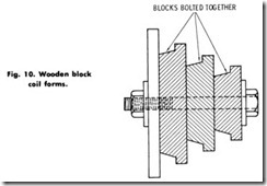
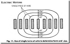
2. Form Winding. Check Figs. 10 and 11. Refer to Form Winding in Chapter 15.
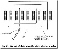
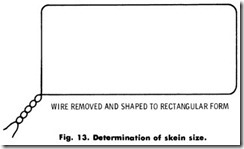
3. Skein Winding. Check Figs. 12 and 13. Also refer to Chapter 15 for machine and form winding of coils and their placement.
Polyphase Stators
Most polyphase fractional horsepower motors are diamond-shaped, mush-wound coils arranged in lap winding. Usually there are as many coils as there are slots, or, in other words, two coil sides per slot, making what is known as a two-layer winding. All the coils are identical in number of turns and size of wire, and the phase coils usually are separated by a strip of insulation (a phase coil is a coil adjacent to a coil of a different phase). The coils are wound or connected in groups.
A group is simply a given number of individual coils connected in series, with only two leads brought out. The stator winding is then connected from these groups. In a de armature lap winding, all the coils are connected in series and a closed winding is formed. In polyphase stators and wound rotors, the coils are connected in a number of groups.
1. Coils for small stators. In the wound coils used in fractional horsepower motors, it is a fairly common practice to wind all the coils of a single group from a continuous strand of wire, if there are the same number of coils in all groups. This simplifies the final connections of a wound stator or rotor. If, however, the number of coils is not the same in all groups, it may be less confusing to bring out leads for each individual coil and to connect them in groups after the stator is wound.
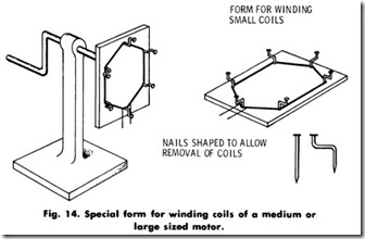
2. Coils for medium sized stators, (Fig. 14). Follow the same procedure in Step 1.
3. Coils for large sized stators. Coils for open-slot stators require a special form and must be wound to conform to the shape of the slot. Their sides must be completely rectangular. Such coils are completely taped.
INSULATING COILS
The procedure for insulating coils for the various applications is found in Chapter 15 under Insulating Coils.
