CONNECTIONS
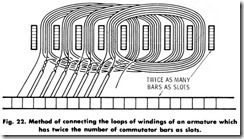
If the coil leads are properly identified, the process of connection is simplified. With the coil sides in their proper slots (coil pitch), which places them in the proper commutating field after connection, the process involves bringing the leads (lead swing) of the coils to the proper commutator bars (commutator pitch), and connecting each individual coil in proper sequence. The procedures outlined below cover the various methods of connecting armature leads to commuta tors. Fig. 22.
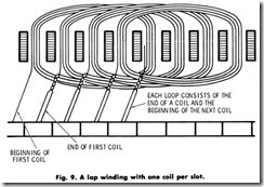
Connecting the Loops of Windings of an Armature which has the Same Number of Commutator Bars as Slots
1. Fill the hollow between the coil ends and the back of the commutator if necessary. (Fig. 9).
2. Determine the proper lead swing or follow the recorded data.
3. Scrape the insulation from the end of the coil-lead loop, coming out of the core slot, used to determine the proper lead swing.
4. Force the scraped coil-lead loop into the proper commutator slot according to the determined or recorded lead swing. If the scraped conductor fits loosely, use more care in the scraping operation so that only the insulation is removed and not the metal.
5. Proceed to the next coil-lead loop and remove the insulation.
Force this coil-lead loop into the bar slot adjacent to the bar in which the first loop was placed, and to the right or left, depending on the lead swing.
7. Follow 5 and 6 above for all the coil-lead loops and commutator bars until all the loops are inserted in the commutator-bar slots progressing to the right, regardless of left or right lead swing.
8. Solder the connections.
9. Band the armature. Banding is shown later in this chapter.
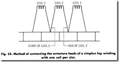
Connecting Leads of a First Coil When There is Only One Start and One Finish Lead for Every Slot (Simplex Lap Winding With One Coil per Slot). (Fig. 23).
1 . Fill the hollow and determine proper lead swing.
2 . Remove the insulation from the end of each coil lead.
3 . Determine or follow the recorded lead swing.
4 . Bend back all finish leads over the core.
5 . Force a start coil lead into the proper commutator-bar slot ac cording to lead swing.
6 . Proceed to the next core slot on the right and force the start coil lead of this slot into the commutator-bar slot adjacent to the right of the first coil start lead.
7 . Follow 6 above for every slot until every commutator-bar slot has a start lead forced into it.
8 . Wrap a layer of cotton or cambric tape over the top of all the start leads between the end windings and the back of the commutator.
9 . Secure the cotton or cambric tape with masking tape.
1 0 . Bring a finish lead forward and down and force it into a bar slot adjacent to the right of the bar in which the start lead of this coil is placed.
1 1 . Bring the next finish lead on the right forward and down and force it into the bar slot adjacent and to the right of the bar slot in which the previous finish lead was forced.
1 2 . Follow 11 above until the commutator is filled.
1 3 . Solder the connections.
1 4 . Band the armature.
Connecting Start Leads of a First Coil When There are Several Leads Identified With One Sleeve, as in the Case of Winding With More Than One Wire in Hand. (Simplex Lap Winding With Two Coils per Slot).
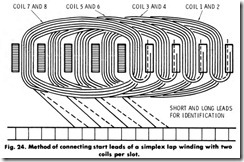
In performing the connecting of start leads of a first coil follow the instructions below: (Fig. 24).
1 . Fill the hollow and determine proper lead swing.
2 . Lift all the finish leads (as determined by the color used for identification of the finish leads) and bend them back over the
armature core.
3 . Select the start leads of the last coil on hand-wound armature or any group of start leads of an armature with preformed coils.
4 . Scrape the insulation from the ends of all leads.
5 . Determine the proper lead swing or follow the recorded data. 6 . Force one start lead of a coil into the proper commutator slot according to the determined or recorded lead swing.
7 . Force the remaining coil start lead of the same group of start leads into the adjacent commutator slot to the right of the first-placed coil start lead.
8 . Proceed to the next core slot and force one of the coil start leads of the coil side into the commutator slot adjacent to the commutator slot which has the last-placed coil start lead of the coil start lead group of the core slot to the left.
9 . Force the remaining coil start lead of the core slot into the adjacent commutator slot, progressing to the right.
1 0 . Perform 8 above for every core slot until all the start leads are placed.
1 1 . Wrap a layer of cotton or cambric tape over the top of all start leads between the end windings and the back of the commutator.
1 2 . Secure this layer with masking tape.
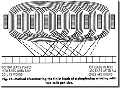
Connecting the Finish Leads of a Simplex Lap Winding With Two Coi Is per Slot
In performing the following steps, extreme care must be exercised, to be sure that improper connection is avoided. (Fig. 25).
1 . Perform a continuity test for locating the coil finish leads of the coil start leads already placed. (Continuity testing is done with a bench-test receptacle and lamp or an ohmmeter.)
2 . Touch one lead of the continuity tester to the commutator bar which has the first coil start lead connected to it. Touch the other continuity-tester lead to each of the finish leads of the coil (several slots away from the core slot where the start leads emerge, according to the coil pitch) until one is found which gives a closed -circuit indication.
3 . Bring the located finish lead forward and down, and force it into the commutator-bar slot, two bars away from the commutator bar on the left, which has the first coil start lead connected.
4 . Bring the remaining coil finish lead for the core slot forward and down, and force it into the bar slot on the left, adjacent to the left of the bar which has the first coil finish lead in it.
5 . Keep the lead of the continuity tester on the same bar started with, advance to the next slot, and with the other continuity-tester lead, touch each of the coil finish leads until one is found which gives a closed-circuit indication.
6 . Bring this lead forward and down, and force it into the bar slot on the left, two bars to the right of the last-placed coil finish lead.
7 . Bring the remaining lead of the slot forward and down, and force it into the bar slot on the right, adjacent and to the right of the last-placed finish lead.
8 . Continue by following 6 and 7 above until all leads are down and placed, moving the continuity-tester lead on the commutator to the right only when necessary for convenience, but never past the commutator bars with connected coil finish leads.
9 . Solder the connections.
1 0 . Band the armature.
Connecting the Leads of a First Coil When There are Several Leads Identified With One Sleeve, as is the Case of Winding With More than One Wire in Hand. (Simplex Lap Winding With Three Leads).
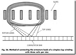
In this type of connection follow the steps indicated below: (Fig. 26)
1 . Follow Steps 1 to 12 of Connecting Start Leads of a First Coil-With More than One Wire in Hand. Also follow steps 1
and 2 above. For 7 above, insert the two remaining coil start leads in adjacent bar slots, to the right of the first coil start leads.
2 . Bring the located finish lead forward and down, and force it in the commutator bar slot, three bars away from the commutator bar on the left which has the first coil start lead connected.
3 . Keep the lead of the continuity tester on the commutator bar which has the first coil start lead connected to it, and touch the other continuity-tester lead to the remainder of the finish leads of the coil (several slots away from the core slot where the start leads emerge·, according to coil pitch) until one is found which gives a closed-circuit indication.
4. . Bring the located finish lead forward and down, and force it into the commutator bar slot on the left, adjacent and to the left of the bar which has the first-located finish coil lead in it.
5. Bring the remaining finish lead of the slot forward and down, and force it into the bar slot on the left, adjacent and to the left of the bar which has the second-located finish coil lead in it.
6. Keep the lead of the continuity tester on the same bar started with, advance to the next slot, and, with the other continuity-tester lead, touch each of the coil finish leads until one is found which gives a closed-circuit indication.
7. Bring this lead forward and down, and force it into the bar slot on the left, three bars to the right of the last-placed coil finish lead.
8. Keep the lead of the continuity tester on the same bar started with, and, with the other test lead, touch each of the remaining coil finish leads until one is found which gives a closed circuit indication.
9. Bring this lead forward and down, and force it into the bar slot on the left, adjacent and to the left of the last-placed coil finish lead.
1 0 . Bring the remaining lead of the slot forward and down, and force
it into the bar slot on the left, adjacent and to the left of the last-placed finish lead.
1 1 . Continue by following 1 to 10 above until all leads are down and placed, moving the continuity-tester lead on the commutator to the right only when necessary for convenience, but never past the commutator bars with connected coil finish leads.
1 2 . Solder the connections.
1 3 . Band the armature.
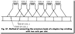
Connecting Leads of a First Coil When There are Several Leads Identified with One Sleeve, as is the Case of Winding With More Than One Wire in Hand. (Duplex Lap Winding With Two Coi Is per Slot)
In performing the following, extreme care must be exercised to be sure that improper connection is avoided. (Fig. 27)
1. Perform a continuity test for locating the coil finish leads of the coil start leads already placed.
2. Touch one lead of the continuity tester to the commutator bar which has the first coil start lead connected to it. Touch the other continuity-tester lead to each of the finish leads of the coil (several slots away from the core slot where the start leads emerge, according to the coil pitch), until one is found which gives a closed circuit indication.
3. Bring the located finish lead forward and down, and force it into the commutator-bar-slot, two bars away from the commutator bar on the left which has the first coil start lead connected.
4. Bring the remaining coil finish lead for the core slot forward and down, and force it into· the bar slot on the left, adjacent and to the right of the bar which has the first coil finish lead in it.
5. Keep the lead of the continuity tester on the same bar started with, advance to the next slot, and, with the other continuity-tester lead, touch each of the coil finish coil leads until one is found which gives a closed-circuit indication.
6. Bring this lead forward and down, and force it into the bar slot on the left, adjacent and to the right of the last-placed coil finish lead.
7. Bring the remaining lead of the core slot forward and down, and force it into the bar slot on the left, adjacent and to the right of the last-placed coil finish lead.
8. Continue by following 6 and 7 above, until all leads are down and placed. Move the continuity-tester lead on the commutator to the right only when necessary for convenience, but never past the commutator bars with connected coil finish leads.
9. Solder the connections.
1 0 . Band the armature.
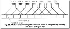
Connecting Leads of a First Coil When There are Several Leads Identified With One Sleeve, as is The Case of Winding With More Than One Wire in Hand. (Triplex Lap Winding With Three Coils per Slot)
1. Follow steps 1 to 12 of the Duplex Lap Winding With Two Coils per Slot, and steps 1 and 2 above. For step 7 above insert the two remaining coil start leads in adjacent bar slots to the right of the first coil start leads. (Fig. 28)
2. Bring the located finish lead forward and down, and force it into the commutator-bar slot three bars away from the commutator bar on the left, which has the first coil start lead connected.
3. Keep the lead of the continuity tester on the commutator bar which has the first coil start lead connected to it. Touch the other continuity-tester lead to the remainder of the coil finish leads of the coil (several slots away from the core slot where the start leads emerge, according to coil pitch) until one is found which gives a closed-circuit indication.
4. Bring the located finish lead forward and down, adjacent and to the right of the bar which has the first-located coil finish lead in it.
5. Bring the remaining finish lead of the slot forward and down, and force it into the bar slot on the left, adjacent and to the right of the bar which has the second-located coil finish lead in it.
6. Keep the lead of the continuity tester on the same bar started with, advance to the next slot, and with the other continuity-tester lead, touch each of the coil finish leads until one is found which gives a closed -circuit indication.
7. Bring this lead forward and down, and force it into the bar slot on the left, adjacent and to the right of the last placed coil finish lead.
8. Keep the lead of the continuity tester on the same bar started with, and, with the other test lead, touch each of the remaining coil finish leads until one is found which gives a closed-circuit indication.
9. Bring this lead forward and down, and force it into the bar slot on the left, adjacent and to the right of the last-placed coil finish lead.
1 0 . Bring the remaining lead of the slot forward and down, and force it into the bar slot on the left, adjacent and to the right of the last placed coil finish lead.
1 1 . Continue by following 6 to 10 above until all leads are down and placed, moving the continuity tester lead on the commutator to the right only when necessary for convenience, but never past the commutator bars with connected coil finish leads.
Connecting Wave-Wound Armature
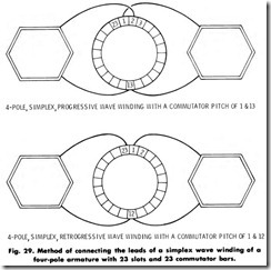
Wave-winding connections are made quite far apart on the commu tator. For examples, as already stated, for a four-pole motor, the winding end leads are connected on opposite sides of the commutator. Any four-pole, wave-wound armature must have an odd number of commutator bars. If the commutator has an even number of bars, two of them must be shorted. In all two-coil-per-slot, four-pole, wave-wound armatures, it is necessary to add a coil in the form of jumper lead. Where the number of bars is one more than the number of coils, and where the number of bars are even, there is a wound coil on the armature which is not connected. The dead coil must remain in the armature for mechanical balancing. The procedures outlined below are for the connection of typical wave-winding leads.
1. Connecting a simplex wave winding of a four-pole armature with 23 slots and 23 commutator bars. For a simplex progressive winding, see 1 of Fig. 29. For a simplex retrogressive winding of an armature see 2 of Fig. 29.
(a) Fill the hollow between the coil ends and the back of the commutator if necessary.
(b) Remove the insulation from the end of each coil lead.
(c) Determine the proper lead swing or follow the recorded data.
(d) Bend back all finish leads over the core.
(e)Force a coil start lead into the proper commutator slot ac cording to the determined or recorded lead swing.
(f) Proceed to the next core slot and place the coil start lead in the bar, adjacent and to the right of the first-placed coil start lead.
(g) Follow a through f above for every one of the coil start leads between the end windings and the back of the commutator.
(h) Wrap a layer of cotton or cambric tape over the top of all the start leads between the end windings and the back of the commutator.
(i) Secure the cotton or cambric tape with masking tape.
(j) Bring a finish lead forward and down, and force it into a bar slot far to the right, according to the proper commutator pitch recorded or calculated.
(k) Bring the next coil finish lead forward and down, and force it into the bar slot far to the right and adjacent to the right of the coil finish lead previously placed.
(l) Follow k above until the commutator is filled.
(m)Solder the connections.
(n) Band the armature.
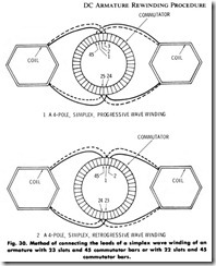
2. Connecting a simplex wave winding of a four-pole armature with 23 slots and 45 commutator bars or with 22 slots and 45 commu tator bars. For a simplex progressive winding see 1, Fig. 30. For a simplex retrogressive winding, see 2 of Fig. 30.
(a) Follow the procedure outlined in a to I of the previous connection steps.
(b) On a 23-slot armature there is 1 coil start lead and 1 coil finish lead which cannot be connected. Tape these leads and follow d and e below.
(c) On a 22-slot armature there are 2 commutator bars without any connections. Connect a jumper between the empty com mutator bars and follow d and e below.
(d) Solder the connections.
(e) Band the armature.
BANDING THE ARMATURE
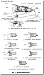
Some open-slot types of armatures require steel-wire bands to prevent the coils from flying out of the slots while the armature is rotating. Steel-wire bands are placed on the front and back ends of the core, the number of bands depending on the size of the armature. This procedure is illustrated in 1 of Fig. 31.
1. Place and center the armature in a lathe.
2. Place insulating paper or mica in the band slot around the entire armature.
3. Tie the insulation in place with one turn of the cord.
4. Prepare small strips of tin or copper, of the appropriate width for the size of the armature and banding slot, and of sufficient length to overlap the banding wire.
5. Insert the strips under the cord equal-distant around the arma ture-band slot.
6. Use the proper gauge steel-banding wire.
7. Place the reel of steel-banding wire in a wire-reel stand with a suitable tensioning device to keep the wire reel from unraveling when the steel-wire banding operation is at rest. Do not release the end of the steel banding wire until the wire spool is on the reel stand. Set the tensioning device to prevent the spring of the turns of steel wire from setting the spool in motion and causing the wire to snarl. Release the end of the wire, but do not let go of it. While working with the wire, constantly keep hold of it until it is firmly anchored on the armature.
8. Pass the end of the wire between the tension blocks.
9. Make one turn around a banding slot, passing the end of the wire over the top of the armature. Anchor the end of the wire, passing it over top of the wedge in the slot on the left and then bringing it down to the shaft. This is done by making two turns around the shaft and twisting the end back on the wire a few times.
1 0 . Set the tension blocks sufficiently to give firm and tight winding on the armature.
1 1 . Remove the tied cord.
1 2 . Start the lathe on slow speed in the direction away from you.
1 3 . Guide the wire onto the armature with a folded piece of insulation paper held in the hand. A glove worn on the hand in contact with the wire would also suffice for protection.
1 4 . Be sure that each turn comes up close to the preceding turn without overlapping.
1 5 . Continue until the entire width of the banding slot is filled; then stop the lathe.
1 6 . Bend over the right tab on all the strips while the lathe is at rest.
Do not cut the steel wire until step 17, 18, and 19 below have been completed.
1 7 . Tin the top right tab with a soldering iron.
1 8 . Bend the left tab over top of the top right tab, bringing it down as close as possible.
1 9 . Apply the soldering iron to the top of the tab causing the tabs to sweat together.
2 0 . Cut the steel wire close to the soldered clamp.
2 1 . Let the end of the wire rest on the lathe bed.
2 2 . Turn the lathe by hand and bring the tabs of another wire clamp on top.
2 3 . Follow 18, 19 and 22 above until all the wire clamps are soldered.
2 4 . Remove the anchoring end of the wire from around the shaft and trim it close to the wire clamp.
2 5 . Repeat 2 to 5 and 9 to 24 above for each of the bands which are required for the armature.
For cord banding an armature the following steps are to be taken. Use enough pressure in winding so that the band will be tight. Use the proper size of banding cord (determined by the size of the armature); light for small armatures, heavy for larger armatures. Refer to steps 1 through 7 of 2, Fig. 31.
1. Start just behind the commutator risers, allowing about 6 inches of the free end of the cord to lay at right angles to the circumfer ence of the armature, pointing toward the core slots.
2. Wind about eight turns onto the armature, each turn against the other firmly and tightly, progressing toward the core slots and over the free end at right angles to the winding.
3. Loop the free end under the winding and back on itself.
4. Wind more turns (at least as many as put on at first) over the loop ends, each turn against the other firmly and tightly, progressing toward the core slots.
5. Bring the winding end of the cord through the loop and pull it up tightly.
6. Pull on the free end of the loop to bring the winding end under the turns of the cord and out between the turns.
7. Cut the two free ends, now emerging from between the turns close to the turns and smooth out the turns so that the point where the free ends emerged will be even.
TESTING
It is very important to test an armature after winding for shorts, opens, or grounds. If all of the precautions are observed and carried out in the rewinding procedure, the possibility of trouble is minimized.
SUMMARY
The process of insulating an armature core, preparatory to rewinding, is one of the most important steps in the rewinding procedure. After the old winding has been removed, the core slots, core ends, and the shaft must be thoroughly cleaned of all insulation and varnish.
Core ends and shaft must be insulated. The commutator of a large armature merely requires bolting the commutator into place when replacing it. After the commutator is placed on the shaft, the hollow between the core and the back of the commutator must be filled. Insulating paper comes in sheets, strips, or cuffed strips in various thicknesses.
It is impractical to use preformed windings on small armatures. End room is limited and the windings must be drawn up tightly to the armature core. In large production shops the small armatures are machine wound on special equipment designed for the purpose.
A hand winding is defined according to the method by which it is wound. There are five methods of hand winding. Slot wedges are used for securing windings in slots. Leads must be properly identified when winding coils. Otherwise making connections will be highly complex and, in some cases, practically impossible.
Very often a rewinding job is made easier by preforming the coils and then placing them in slots. This may be done in a number of ways.
Slots of large armatures and stators are generally open and the coils are usually completely taped. Cotton tape is often used for this purpose, with varnished cambric and mica preferred for large motors and special applications. In medium-sized motors the slots are generally semi closed.
The placement of preformed coils into the slots is dependent upon the type of slot. Care must be taken so that conductors are not scraped. Wrappings must stay intact and insulations not disturbed. There are semi-closed and open slots in motors.
If the coil leads are properly identified, the process of connection is simplified. With the coil sides in their proper slots, which places them in the proper commutating field after connection, the process involves bringing the leads (lead swing) of the coils to the proper commutator gears (commutator pitch), and connecting each individual coil in proper sequence.
Some open-slot types of armatures require steel-wire bands to prevent the coils from flying out of the slots while the armature is rotating. Steel-wire bands are placed on the front and back ends of the core, the number of bands depending upon the size of the armature.
It is very important to test an armature after winding for shorts, opens, and grounds. If all the precautions are observed and carried out in the rewinding procedure, the possibility of trouble is minimized.
REVIEW QUESTIONS
1. What is the difference between the slots in a large and a medi- um-sized armature?
2. What determines the placement of preformed coils in slots?
3. Why do some armatures require steel-wire bands?
4. Why should you test an armature before assembling a motor?
5. What is the most important step in rewinding a motor?
6. How can insulating paper be purchased for motor rewinding?
7. Why is it impractical to use preformed windings on small arma tures?
8. Name the five methods of hand winding an armature.
9. What does the motor rewinder use to secure windings in slots?
10. How are leads identified during the rewinding process?
