PERMANENT SPLIT-CAPACITOR MOTOR
The permanent split capacitor (PSC) motor is used in compressors for air conditioning and refrigeration units. It has an advantage over the capacitor start motor inasmuch as it does not need the centrifugal switch and its associated problems.
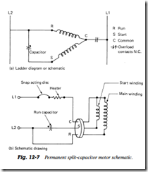
The PSC motor has a run capacitor in series with the start winding. Both run capacitor and start winding remain in the circuit during start and after the motor is up to speed. Motor torque is sufficient for capillary and other self equalizing systems. No start capacitor or relay is necessary. The PSC motor is basically an air conditioner compressor motor. It is very common upto 3 hp, but is also available in the 4 and 5 hp sizes (Fig. 12 7).
SHADED-POLE MOTOR
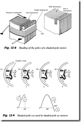
The shaded pole induction motor is a single phase motor. It uses a unique method to start the rotor turning. The effect of a moving magnetic field is produced by constructing the stator in a special way (Fig. 12 8). Portions of the pole piece surfaces are surrounded by a copper strap called a shading coil. The strap causes the field to move back and forth across the face of the pole piece
In Fig. 12 9, the numbered sequence and points on the magnetization curve are shown. As the alternating stator field starts increasing from zero (1), the lines of force expand across the face of the pole piece and cut through the strap. A voltage is induced in the strap. The current that results generates a field that opposes the cutting action (and decreases the strength) of the main field. This action causes certain actions: As the field increases from zero to a maximum of 90, a large portion of the magnetic lines of force are concentrated in the unshaded portion of the pole (1). At 90 the field reaches its maximum value. Since the lines of force have stopped expanding, no EMF is induced in the strap, and no opposite magnetic field is generated. As a result, the main field is uniformly distributed across the poles as shown in (2).
From 90 to 180 the main field starts decreasing or collapsing inward. The field generated in the strap opposes the collapsing field. The effect is to concentrate the lines of force in the shaded portion of the poles as shown in (3).
Note that from 0 to 180, the main field has shifted across the pole face from the unshaded to the shaded portion. From 180 to 360, the main field goes through the same change as it did from 0 to 180. However, it is now in the opposite direction (4). The direction of the field does not affect the way the shaded pole works. The motion of the field is the same during the second halfhertz as it was during the first half hertz
The motion of the field back and forth between shaded and unshaded portions produces a weak torque. This torque is used to start the motor. Because of the weak starting torque, shaded pole motors are built in only small sizes. They drive such devices as fans, clocks, and blowers
Reversibility
Shaded pole motors can be reversed mechanically. Turn the stator housing and shaded poles end for end. These motors are available from 1/250 to 1/2 hp.
Uses
As mentioned previously, this type of motor is used as a fan motor in refrigerators and freezers. They can also be used as fan motors in some types of airconditioning equipment where the demand is not too great. They can also be used as part of the timing devices used for defrost timers and other sequenced operations
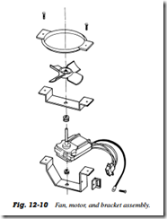
The fan and motor assembly are located behind the provisions compartment in a refrigerator, directly above the evaporator in the freezer compartment. The suction fan pulls air through the evaporator and blows it through the provisions compartment air duct and freezer compartment fan grille (Fig. 12 10). This is a shaded pole motor with a molded plastic fan blade. For maximum air circulation the location of the fan on the motor shaft is most important. Mounting the fan blade too far back or too far forward on the motor shaft, in relation to the evaporator cover, will result in improper air circulation. The freezer compartment fan must be positioned with the lead edge of the fan 1/4 in in front of the evaporator cover
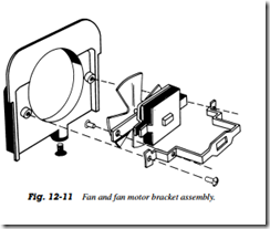
The fan assembly shown in Fig. 12 11 is used on the top freezer, no frost, fiberglass insulated model refrigerators. The freezer fan and motor assembly is located in the divider partition directly under the freezer air duct


