Electric Braking
A motor and its load may be brought to rest quickly by using either (i) Friction Braking or (ii) Electric Braking. The commonly-used mechanical brake has one drawback : it is difficult to achieve a smooth stop because it depends on the condition of the braking surface as well as on the skill of the operator.
The excellent electric braking methods are avail- able which eliminate the need of brake lining levers and other mechanical gadgets. Electric braking, both for shunt and series motors, is of the following three types: (i) rheostatic or dynamic braking
(ii) plugging i.e., reversal of torque so that armature tends to rotate in the opposite direction and
(iii) regenerative braking.
Obviously, friction brake is necessary for holding the motor even after it has been brought to rest.
Electric Braking of Shunt Motors
(a) Rheostatic or Dynamic Braking
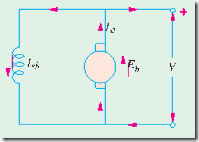
In this method, the armature of the shunt motor is disconnected from the supply and is connected across a variable resistance R as shown in Fig. 30.21 (b). The field winding is, however, left connected across the supply undisturbed. The braking effect is controlled by varying the series resistance R. Obviously, this method makes use of generator action in a motor to bring it to rest.* As seen from Fig. 30.21
(b), armature current is given by
Obviously, TB decreases as motor slows down and disappear altogether when it comes to a stop.
(b) Plugging or Reverse Current Braking
This method is commonly used in controlling elevators, rolling mills, printing presses and machine tools etc.
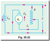
In this method, connections to the armature terminals are reversed so that motor tends to run in the opposite direction (Fig. 30.22). Due to the reversal of armature connections, applied voltage V and Eb start acting in the same direction around the circuit. In order to limit the armature current to a reasonable value, it is necessary to insert a resistor in the circuit while reversing armature connections.
Plugging gives greater braking torque than rheostatic braking. Obviously, during plugging, power is drawn from the supply and is dissipated by R in the form of heat. It may be noted that even when motor is reaching zero speed, there is some braking torque TB = k4 (see Ex. 30.47).
 (c) Regenerative Braking
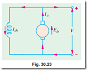
This method is used when the load on the motor has over- hauling characteristic as in the lowering of the cage of a hoist or the downgrade motion of an electric train. Regeneration takes place when Eb becomes grater than V. This happens when the overhauling load acts as a prime mover and so drives the machines as a generator. Consequently, direction of Ia and hence of armature torque is reversed and speed falls until Eb becomes lower than V. It is obvious that during the slowing down of the motor, power is returned to the line which may be used for supplying another train on an upgrade, thereby re- lieving the powerhouse of part of its load (Fig. 30.23).
For protective purposes, it is necessary to have some type of mechanical brake in order to hold the load in the event of a power failure.
Example 30.46. A 220 V compensated shunt motor drives a 700 N-m torque load when running at 1200 r.p.m. The combined armature compensating winding and interpole resistance is 0.008 W and shunt field resistance is 55 W. The motor efficiency is 90%. Calculate the value of the dynamic braking resistor that will be capable of 375 N-m torque at 1050 r.p.m. The windage and friction losses may be assumed to remain constant at both speeds.


