MONOCHROME TV STANDARDS AND SYSTEMS
The word television means viewing from a distance. In a broader sense, television is the transmission of picture information over an electric communication channel. It is desired that the picture picked up by television receiver be a faithful reproduction of the scene televised from a TV studio. Any scene being televised has a wide range of specific features and qualities. It may contain a great number of colours, gradations of shade, coarse and fine details; motion may be present in a variety of forms and the objects making up the scene are usually in three dimensions.
In the early 20th century, TV systems, primitive from the standpoint of the present day, were mechanical. Today, TV equipment is all electronic. The replacement of mechanical by electronic television has made it possible to reproduce a high- quality picture approaching the original scene in quality.
ELEMENTS OF A TELEVISION SYSTEM
Television is an extension of the science of radio communications, embodying all of its fundamental principles and possessing all of its complexities and, in addition, making use of most of the known techniques of electronic circuitry.
In the case of the transmission and reproduction of sound, the fundamental problem is to convert time variations of acoustical energy into electrical information, translate this into radio frequency (RF) energy in the form of electromagnetic waves radiated into space and, at some receiving point, reconvert part of the resultant electromagnetic energy existing at that point into acoustical energy.
In the case of television, there is the parallel problem of converting space and time variationsof luminosity into electrical information, transmitting and receiving this, as in the case of sound, and reconverting the electrical information obtained at a receiving location into an optical image.
When the information to be reproduced is optical in character, the problem fundamentally is much more complex than it is in the case of aural information. In the latter instance, this is dealt with at each instant of time only a single piece of information, since any electrical waveform representing any type of sound is a single-valued function of time regardless of the complexity of the waveform. In the corresponding optical case, at any instance there is an infinite number of pieces of information existing simultaneously namely, the brightness which exists at each point of the scene to be reproduced. In other words, the information is a function of two variables, time and space. Since the practical difficulties of transmitting all this information simultaneously and decoding it at the receiving end at the present time seem insurmountable, some means must be found whereby this information may be expressed within the form of a single-valued function of time. In this conversion, the process known as scanning plays a fundamental part.
THE SCANNING PROCESS
Scanning may be defined as the process which permits the conversion of information expressed in space and time coordinates into time variations only. Suppose, for extreme simplicity, that an optical image of a scene, perhaps on a photosensitive surface, is scanned by a beam of electrons, i.e. all points on the image are sequentially contacted by this beam, and that somehow, as a result of this scanning, through capacitive, resistive, or photoemissive effects at the surface, an electrical signal may be obtained that is directly proportional in amplitude to the brightness at the particular point being scanned by the beam. Although the picture content of the scene may be changing with time, if the scanning beam moves at such a rate that any portion of the scene content does not have time to move perceptibly in the time required for one complete scan of the image, the resultant electrical information contains the true information existing in the picture during the time of the scan. This derived information is now in the form of a signal varying with time.
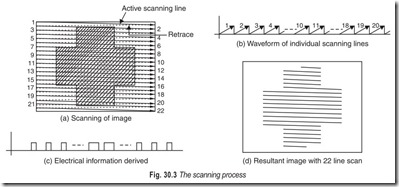
Consider the image of Fig. 30.3 (a). The light and dark areas represent variations in brightness of the original scene. Suppose that a beam of electrons is made to scan this image as shown, starting in the upper left hand corner and moving rapidly across the image in a time t, thus forming line 1 as shown, and then made to return instantaneously. This process is repeated until the bottom of the image is reached. The time variation of the horizontal component of motion of the scanning beam is that shown in Fig. 30.3 (b).
Means exist whereby an electrical signal corresponding in amplitude to the illumination on the point being scanned may be derived. The electrical output as a function of time corresponding to individual scanning lines is shown in Fig. 30.3 (c). This electrical information corresponding to the light intensity of a large sampling of points in the original scene is now obtained, with the limitation that the detail which can be reproduced depends on the completeness of coverage by the scanning beam. This coverage is determined directly by the total number of scanning lines. If the scanning beam is now made to return to the top of the picture and this process is repeated, another sampling of information identical with the first will be obtained unless the scene has changed in the meantime, in which case the new sampling of information will be in accordance with this change.
At the receiving end, the fundamental problem is that of recombining the information, which has been broken down into a time function, into an optical image. The image which is reproduced, with the number of lines shown, is indicated in Fig. 30.3 (d).
SCANNING METHODS AND ASPECT RATIO
The scanning mechanism is the portion of the entire television system which deserves the most attention from the standpoint of the necessity of formulation of standards of methods and performance. Once the scanning system is standardised, the performance of the system is specifically limited.
The process of scanning makes possible the use of a single transmission channel. Otherwise there would be required as many transmission channels as there are simultaneous units of optical information to be reproduced.
In the scanning process the amount of detail actually converted to useful information depends on the total percentage of picture area actually contacted by the electron beam. The scanning process is such that the picture area is traversed at repeating intervals, giving in effect a series of single pictures much in the same manner that motion pictures are presented. The repetition rate of these successive pictures (referred to as frame rate) determines the apparent continuity of a moving scene. This rate must be chosen sufficiently high so that neither discontinuity of motion nor flicker is apparent to the eye.
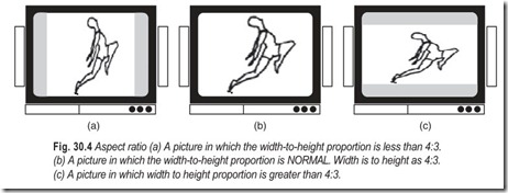
The scanning method chosen might depend on the geometry of the image to be reproduced. It is logical that the geometry should be chosen by the viewer of the final reproduced picture. Here it is useful to rely on the experience of the motion-picture industry, which until the advent of stereo techniques reproduced a rectangular pattern having an aspect ratio (picture width to picture height) of approximately 4 : 3. Most subjective tests have indicated that aspect ratios approximating 4 : 3 are most pleasing artistically and less fatiguing to the eye. A physiological basis for this might be that the eye is less restricted in its range of movement in a horizontal than in a vertical direction. Also, the fovea, or area of greatest resolution, is some what wider than it is high. Thus, the area of the fovea is most efficiently utilised.
Once the geometry of the image has been specified, it remains to determine what sequence may be used by the scanning beam to cover the entire area. For a picture of rectangular geometry, any form of spiral or
circular scanning would be wasteful of scanned area. Also, scanning of this type would result in nonuniform coverage of the area or in varying scanned velocities. A varying scanning velocity for the pick-up and reproducing devices results in varying output for constant scene brightness. Correction for this would be necessary.
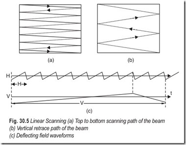
Most practical television systems, therefore, resort to linear scanning of the image. Also, it is common practice to scan the image from left to right, starting at the top and tracing successive lines until the bottom of the picture is reached, then returning the beam to the top and repeating the process. This is shown in Fig. 30.5 (a). The direction of the arrows on the heavy lines indicates the forward (trace) or useful scanning time. The dashed lines indicate the retrace time, which is not utilised in converting picture information into useful electrical information. The movement during the return of the scanning spot to the top of the image is shown in Fig. 30.5(b).
This is the type of scan which would result in a cathode ray device when the scanning-spot position is determined by the horizontal and vertical components of electric or magnetic fields where these components are repeating linear functions of time as shown in Fig. 30.5 (c). If the repetition rate of the horizontal component is related to that of vertical component by a factor n, then n lines are formed during a complete vertical period. The retrace times, both horizontal and vertical, are not utilised for transmitting a video signal but may be employed for the transmission of auxiliary information such as teletext, for example.
PERSISTENCE OF VISION AND FLICKER
The image formed on the retina is retained for about 20 ms even after optical excitation has ceased. This property of the eye is called persistence of vision, an essential factor in cinematography and TV for obtaining the illusion of continuity by means of rapidly flashing picture frames. If the flashing is fast enough, the flicker is not observed and the flashes appear continuous. The repetition rate of flashes at and above which the flicker effect disappears is called the critical flicker frequency (CFF). This is dependent on the brightness level and the colour spectrum of the light source.
In cinema, a film speed of 16 frames per second was used in earlier films to obtain the illusion of movement. Lack of smooth movement was noticeable in these films. The present day standard for movie film speed is 24 frames per second and at this speed, flicker effects are very much reduced. This problem is further reduced in modern projectors by causing each frame to be illuminated twice during the interval it is shown by means of fan blades. The resulting flicker rate is quite acceptable for cine screen projection, because it is viewed in subdued light and a wide display area.
In television, the field rate is concerned with (i) large area flicker, (ii) smoothness of motion, and (iii) motion blur in the reproduced picture. As the field rate is increased, these parameters show improvements but tend to saturate beyond 60 Hz. Further increase does not pay off, and increases the bandwidth. Hence the picture field scanning is generally done at the same rate as the mains power supply frequency, which conveniently happens to be 50 or 60 Hz for the same reasons of reducing illumination flicker from electric lamps. At 60 Hz the flicker is practically absent. At 50 Hz, a certain amount of borderline flicker may be noticed at high brightness levels used to overcome surrounding ambient light conditions. Use of commercial power frequency for vertical scanning also reduces possible effects, like supply ripple and 50 Hz magnetic fields, in the reproduced picture.
VERTICAL RESOLUTION
An electron beam scanning across a photosensitive surface of a pick-up device can be made to produce in an external circuit a time-varying electrical signal whose amplitude is at all times proportional to the illumination on the surface directly under the scanning beam. The upper frequency limit of the amplifier for such signals depends upon the velocity of the scanning beam.
Most scenes have brightness gradations in a vertical direction. The ability of a scanning beam to allow reproduction of electrical signals corresponding to these gradations may be seen to be dependent upon the number of scanning lines and not upon the velocity of the individual scanning lines. However, the two are integrally related if the picture-repetition rate and the number of lines are fixed.
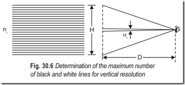
scan ratio of a television system. The realistic limit to the number of lines is set by the resolving capability of the human eye, viz. about one minute of visual angle. For comfortable viewing an angle of about 10 to 15° can be taken as the optimum visual angle. Hence the best viewing distance for watching television is about 4 to 8 times the height of the picture, i.e. a visual angle of about 10° as shown in Fig. 30.6.
The maximum number of dark and white elements which can be resolved by the human eye in thevertical direction in a screen of height H is given by nv according to the relation:
H/D = nv × αo …(30.1)
where nv is the number of black and white lines of vertical resolution, αo is the minimum angle of resolution in radians and D the distance of the viewer.
Problem 30.1 Calculate the number of black and white lines of vertical resolution for a visual angle of about 10°.
Solution When αo equals 10°, D/H = 6
Problem 30.2 Calculate the number of black and white lines of vertical resolution for a visual angle of about 15°.
Solution When αo equals 15° D/H = 4
The number of alternate black and white elementary horizontal lines which can be resolved by the eye
are thus 600 for 10° visual angle and 900 for a 15° visual angle. There has been a large difference of opinion about what constitutes the maximum number of lines because of the subjective assessment involved. This has been made further difficult to assess because of the effects of the finite size of the scanning beam spot.
PICTURE ELEMENTS
A picture element (pixel) is the smallest area in an image that can be reproduced by the video signal. The size of a pixel depends upon the size of the scanning spot, the number of scanning lines and the highest frequency utilised in the video signal. Its vertical dimension is equal to the distance between two scanning units, or centre to centre distance between two adjacent spots. Its horizontal dimension will also be the same.
With an aspect ratio of 4:3 the number of pixels on a horizontal scanning line will be 4/3 times the number of pixels on a vertical line. The total number of pixels activated on the screen reproduce the picture.
THE KELL FACTOR
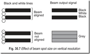
In practical scanning systems, the maximum vertical resolution realised is less than the actual number of lines available for scanning. This is because of the finite beam size and its alignment not coinciding with the elementary resolution lines.
Consider a finite size of a beam spot scanning a series of closely spaced horizontal black and white lines of minimum resolvable thickness, when the beam spot size is compatible with the thickness of the line, as shown in Fig. 30.7. If the beam is in perfect alignment the output will exactly follow the lines as black or white levels. If, however the beam spot is misaligned, it senses both black and white areas simultaneously. Hence, it integrates the effects of both areas to give a resultant grey level output in between the black and white levels. This happens for all scanning positions and the output as well as the reproduced picture is a continuous grey without any vertical resolution at all. In positions of intermediate alignment of beam, it will be more on one line than on the adjacent line and the output will be reproduced with diminished contrast. This indicates that there is a degradation in vertical resolution due to finite beam size.
The factor indicating the reduction in effective number of lines is called the Kell factor. It is not a precisely determined quantity and its value varies from 0.64 to 0.85. What the Kell factor indicates is that it is unrealistic to consider that the vertical resolution is equal to the number of active lines.
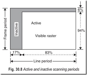
The flyback time also reduces the number of active picture elements as depicted in Fig. 30.8. The horizontal flyback interval occupies 17% of the line period and the vertical flyback interval occupies 6% of the frame period.
In the 625 line system, the number of active lines lost in vertical blanking (referred to as inactive lines) are (625 – 40 =) 585 lines. With a Kell factor of 0.7 (average value) the vertical resolution is (0.7 × 585) = 409.50 lines. The horizontal resolution may not exceed this value multiplied by the aspect ratio.
HORIZONTAL RESOLUTION AND VIDEO BANDWIDTH
The horizontal resolution of a television system is the ability of the scanning system to resolve the horizontal details i.e., changes in brightness levels of elements along a horizontal scanning line. Since such changes represent vertical edges of picture detail, it follows that horizontal resolution can be expressed as a measure of the ability to reproduce vertical information.
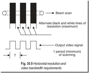
The horizontal resolution in a scanning system depends on the rate at which the scanning spot is able to change brightness level as it passes through a horizontal line across the vertical lines of resolution shown in Fig. 30.9. In the 625 line system, there are about 410 active lines of resolution. With an aspect ratio of 4:3 the number of vertical lines for equivalent horizontal resolution will be (410 × 4/3 =) 546 black and white alternate lines which corresponds to (546 × 1/2 =) 273 cycles of black and white alternations of elementary areas. For the 625 line system, the horizontal scan frequency (line frequency) is given by:
fH= number of lines per picture × picture scan rate
= 625 × 25 = 15, 625 Hz …(30.2)
as each picture line is scanned 25 times per second. The total line period is thus
Out of this period, 12 µs are used for the blanking of flyback retrace.Thus 546 black and white alternations (273 cycles of complete square waves) are scanned along a horizontal line during the forward scan time of (64 – 12 =) 52 µs. The period corresponding to this square wave is 52/273 or 0.2 µs approximately, giving the highest fundamental video frequency of 5 MHz. Thus
where tfH is the horizontal line forward scan period.
The fundamental law of communications, the interchangeability of time and bandwidth states that “if total number of units of information is to be transmitted over a channel in a given time by specified methods, a specific minimum bandwidth is required”. If the time available for transmission is reduced by a factor, or if the total information to be transmitted is increased by the same factor, the required bandwidth is increased by this factor. Suppose for example, the picture detail in both horizontal and vertical directions is to be doubled without changing the frame rate. This represents an increase in total picture elements by a factor of 4.
INTERLACING OF SCANNING LINES
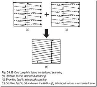
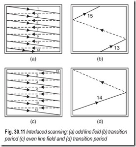
The vertical resolution of a system depends on the total number of active scanning lines, whereas the critical flicker frequency (CFF) is the lowest possible apparent picture repetition rate which may be used without visible flicker. If during one vertical scanning field alternate scanning (odd) lines are formed and during the second scanning field the remaining (even) lines are formed, at the end of the one frame period all the lines are formed. This process called interlaced scanning gives a vertical scanning frequency of twice the true picture-repetition, or frame frequency. The situation is illustrated in Fig. 30.10 and further elaborated in Fig. 30.11.
The upper frequency requirement of the video system is based on the true picture-repetition frequency, whereas the large area flicker effects are based on twice this frequency, or the vertical scanning frequency. The principle of interlacing the scanning lines, therefore, by cutting the complete picture repetition rate in half, allows a system to maintain the same resolution and flicker characteristics as a noninterlaced system with a bandwidth requirement only half that of the noninterlaced system.
Further improvement might result from more complicated interlacing systems. The ratio of field to frame frequency cannot be too great, however, since flicker would begin to show up for small picture areas which would not be covered by all the successive fields making up a complete frame.
The television picture is different from the picture projected in a movie theatre in that it consists of many lines. Another difference is the fact that a projected movie frame appears as a complete picture during each instant it is flashed on the screen. The television picture is traced by a spot of light. When the spot traces a television picture, it does so in the following manner;
(a) The spot traces line 1 of the picture
(b) The spot traces line 3 of the picture
(c) The spot traces line 5 of the picture …….. and so on.
The spot traces all the odd lines of the picture. When the spot reaches the bottom of the picture, it has traced all the odd lines i.e. a total of 312.5 lines in the 625 line system. This is called the odd-line field. Fig.30.11 (a).
After the spot has traced all the odd lines, the screen is blanked and the spot is returned quickly to the top of the screen once again. The time during which the spot travels back to the top of the screen is called the vertical retrace period. The timing of the this period is such that the spot reaches the top centre of the screen when it again starts tracing lines in the picture as shown in Fig. 30.11 (b). On this second tracing, the spot traces,
(a) line 2 of the picture
(b) line 4 of the picture
(c) line 6 of the picture… and so on.
When the spot completes the tracing of all even lines i.e. a total of 312.5 lines in the 625 line system and is at the bottom of the picture, it has traced the even-line field, depicted on Fig. 30.11 (c).
The screen is then blanked once again, and the spot is returned to the top-left-hand corner of the screen, Fig. 30.11(d) and the tracing sequence repeats. The method of scanning, where the odd lines and even lines are alternately traced, is called interlaced scanning.
After both the odd and-even-fields have been scanned, the spot has given us one frame of the television picture. The word frame is borrowed from motion pictures, to indicate one complete picture that appears in a split second. In television, the odd-line field and the even-line field make one frame.
TEST CARD
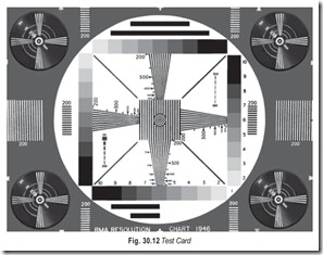
All TV stations transmit a tuning signal for some time before the start of the program proper, to facilitate the tuning in of receivers. The signal takes the form of a Test Card which, besides other geometrical figures, such as checker board pattern, always includes one or more circles and both horizontal and vertical patterns of lines. The circles and other geometrical figures aid in the correction, where necessary, of frame linearity and of aspect ratio. The vertical pattern of lines serves for the fine tuning of channel selector, and the horizontal one for the accurate adjustment of the spacing. Fig. 30.12 shows a test card offering a particularly wide range of possibilities.
You can receive the correct aspect ratio by adjusting for a pattern which resembles, Fig. 30.12 as closely as possible. The wedges in the test pattern should be as close to equal length as possible; the circle should be as round as possible.
THE VIDEO SIGNAL
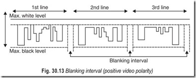
The voltage equivalent of any horizontal line that is scanned begins where the electron beam starts scanning the image horizontally, and ends where the scanning finishes and the horizontal retrace blanking begins. If we assume that the scanning action continues line after line, as happens in television transmitters, we have delivered to the video preamplifier in the camera, a train of picture voltages with intervals of blanking in between. Although the lines scanned are positioned one below the other, the voltage representation of the these lines is a train of voltage fluctuations, one following the other, along a time base. A blanking voltage is applied to the camera tube to extinguish the beam during horizontal retrace, although the signal output from the camera is zero during the blanking interval. In other words, the blanking signal fed to the electron gun of the camera tube does not appear in the camera tube video output. The voltage representation of every line scanned is separated from the next by the blanking interval, Fig. 30.13.
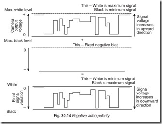
The video output from the iconoscope increases in amplitude as the image changes from black to white and white in the image produces stronger video signal. This is called positive video polarity. In negative video polarity the conditions of operation call for white in the image to produce the theoretically zero signal and black in the image to produce theoretically maximum video signal. The condition of negative video polarity can be met with by applying the iconoscope camera output signal to a negative clamping circuit. This is shown in Fig. 30.14. The whole of the signal then appears below the zero-voltage baseline and is entirely in the zone of negative polarity voltage.
When the fixed negative bias is added to the positive-polarity camera signal, the result is a voltage variation wherein white in the image becomes the least negative voltage and black in the image becomes the most negative voltage.
Before broadcast, the video signal is passed through a number of amplifying stages employing transistors. Each amplifying stage inverts the direction of video signal. It is quite obvious, that a positive polarity video signal can also be converted into a negative-polarity video signal, simply by employing an odd number of amplifying stages.
CONTROL PULSES
TV receivers work precisely to give you a rock steady, crisp and clear picture, accompanied by scintillating melodious sound. You might think that all this calls for a precise, sophisticated and expensive, TV receiver. No doubt, precision is essential in television but it is in the transmitting equipment and not in the receiving equipment. Whether this precision is in the transmitting equipment, or in the receiving equipment, it is immaterial, because anyway it serves the same purpose. To maintain this precision in the transmitting equipment is, of course, convenient, practical, and economical. Where this precision maintained in the receiving equipment, TV receivers would have become complicated, costly, and beyond the repair capability of each and every technician.
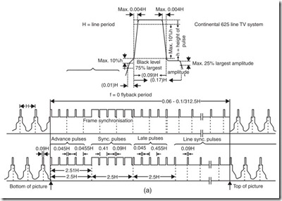
In addition to the normal video and sound, the transmitted signal also contains the following control signals:
(1) line blanking pulses; (2) frame blanking pulses; (3) line synchronising (sync) pulses; (4) frame synchronising (sync) pulses: (5) pre-equalising pulses; and (6) post-equalising pulses.
The video, sound, and control signals combine to make up the composite video signal. Within the TV receiver, the circuits are slaved to this signal. For example, the frame oscillator, if left free, would drift in frequency, resulting in vertical instability. Similarly, the line oscillator, if left free, would also drift in frequency, resulting in horizontal instability. The composite video signal locks in the frequency and phase of the frame and line oscillators.
COMPOSITE VIDEO SIGNAL
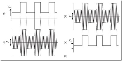
The simple video signal we started with has turned into a video signal which is really complex. The variations of current strength conveying the picture content are here interwoven with a dense system of pulses, Fig. 30.15(a), all working towards a common aim. If this train of pulses has to be transmitted, a method that suggests itself is to modulate the amplitude of the carrier wave in the rhythm of the pulses.
There will have to be an amplitude detector in the receiver to recover this pulse train from the modulated carrier wave. The detector consists of a simple network that transforms high-frequency electrical waves into a direct voltage. The magnitude of the direct voltage produced always corresponds exactly to the strength of the high-frequency wave, and thus it will give an accurate representation of the changes in the amplitude of the wave. The output voltage of the detector will thus have the same pulse like character as the voltage modulating the carrier at the transmitter, Fig. 30.15(b). This method of modulation, whereby the amplitude of the carrier wave is made to vary between a maximum and a minimum is called amplitude modulation (AM).
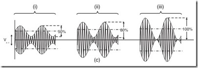
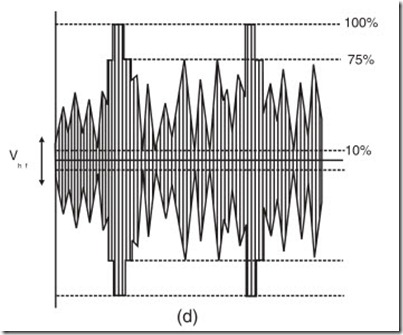
An important characteristic of amplitude modulation is the degree of modulation; it is the difference between maximum and minimum amplitudes of the carrier expressed as percentage of its average amplitude. Sinusoidal modulation with 50%, 80% and 100% depth of modulation is illustrated in Fig. 30.15(c). Full modulation of a carrier wave, to a depth of 100%, is obviously the most efficient, but it is avoided in radio and TV transmitters because it makes accurate demodulation in the receiver a very difficult matter. The picture carrier as modulated with the video signal (negative modulation) is shown in Fig. 30.15(d).
THE HIGHEST VIDEO FREQUENCY
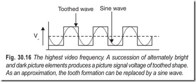
For the picture to be reproduced with sufficient sharpness and wealth of detail, its area must be split up into about 400,000 elements. At the rate of 25 pictures a second, a total of 10,000,000 of these elements will have to be scanned per second. Let us assume an extreme case in which all the elements are alternately bright and dark. The picture signal—the voltage derived from the camera tube—would then be a toothed wave, with five million positive teeth and five million negative gaps, part of which is shown in Fig. 30.16.
Let us further replace this toothed wave with a sine wave (dotted line). This sinusoidal oscillation represents a frequency of 5 MHz. An alternating voltage, with this frequency, is the most rapidly changing one that can arise from the scanning of a picture. This is the highest video frequency of the system and plays a dominant role in the whole chain of transmission, from the scene being televised in the studio to the scene being viewed on the picture tube screen. Obviously, the highest video frequency depends on the number of lines.
THE LOWEST CARRIER FREQUENCY
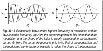
The carrier wave itself must have a frequency far higher than the highest video frequency, otherwise, the shape of the modulation would not be clearly reflected in the modulated carrier. This will be clear from Fig. 30.17.
With a carrier frequency of at least five times as great as the modulation frequency, the modulation shape finds clear expression in the modulated carrier, Fig. 30.17 (a). On the other hand, when carrier frequency is only twice modulation frequency, it is scarcely possible to recognise the shape of the modulation, as shown in Fig. 30.17 (b).
The carrier frequency chosen is, in practice, at least five times as great as the modulation frequency. For television, carrier waves must be used with a frequency higher than about 30 MHz. Colour television transmission only becomes possible in the VHF and higher ranges—that is, on wavelengths under 10 metres. In fact, the lowest frequency officially allocated to television by international agreement is over 40 MHz.
SIDE BAND FREQUENCIES
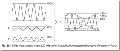
The basic form of any process, that repeats itself periodically, is a pure sine wave of constant amplitude and frequency. Processes of a complicated nature, with amplitude or frequency changing in a haphazard manner, are composed of several elementary sinusoidal oscillations. If a 20 kHz wave is amplitude modulated with a 4 kHz wave, there exist in reality three oscillations having constant amplitude: a stronger oscillation of 20 kHz, and two equally weak oscillations of (20 – 4) = 16 kHz, and (20 + 4) = 24 kHz. The three of them appear one above the other. Adding together the amplitudes of the three waves, point by point, results in the amplitude modulated wave, Fig. 30.18.
Amplitude modulation does not signify the alteration of the carrier wave amplitude, but what happens is that two new waves are formed, arising symmetrically on either side of the carrier. The two new waves are generated automatically in the modulation stage of the transmitter. The new waves arising in this way, are called sideband waves or are referred to collectively as the upper and lower sidebands of the carrier wave.
What happens when the carrier is modulated by some other voltage shape, for example, a video signal which, of course, is not sinusoidal. Completely irregular, as the video information is, and dependent only on differences of brightness between individual picture elements, the video signal is, in reality, made up of a great number of pure sinusoidal oscillations, having various amplitudes and frequencies. This mixture of frequencies consists of two distinct groups of waves. The first group includes all waves with a frequency that is a multiple of the line frequency. In the 625 line system, the line frequency is 25 × 625 = 15,625 Hz, and this group, therefore, includes the following frequencies 15,625 Hz; 2 × 15,625 = 31,250 Hz; 3 × 15,625 = 46,875 Hz; 4 × 15,625 = 62,500 Hz and so on. The wave of frequency 15,625 Hz is called the fundamental. The waves having twice, three times, and four times the fundamental frequency are called the second, third and fourth harmonics of the fundamental.
The second group of waves, contained in the video signal covers the picture frequency of 25 Hz, and its harmonics, i.e, 50,75,100 Hz and so on. In the composite video signal, the two groups of waves are so combined that an upper and lower sideband each consisting of a complete group of waves, made up of the picture frequency and its harmonics, is arranged symmetrically around each harmonic of the line frequency i.e. at 15,625; 31,250; 46,875 Hz etc. This is illustrated in Fig. 30.19.
The waves of the first group are the predominant ones, while the sidebands of the 25 Hz group play only a subordinate part and quickly tail off in amplitude. This frequency spectrum, as it is called, exhibits the enormous number of pure sinusoidal oscillations, that go to make up the composite video signal, resulting from the scanning of a picture. We need take into account only frequencies upto 5 MHz. The finest picture detail is carried by still higher frequencies, but these are beyond the power of resolution possessed by the human eye.
A whole band of frequencies is produced in the modulation stage of a transmitter. The whole of this band has to be radiated by the transmitting antenna, taken up by the receiving antenna, and amplified in the receiver, in order that it can be finally changed back to its original form, the video signal in the demodulation stage.
This emphasizes the necessity for all the links in the chain of transmission to have sufficient bandwidth. This means that the transmitting and receiving antennas must respectively radiate and take up all the waves from the lowest to the highest sideband frequency, with the same efficiency; it also means that the receiver must amplify all these frequencies to the same extent. If this is not so, and some of the waves are somehow handicapped during their journey, then the picture signal recovered in the demodulation stage will have a form different from the original. As an example, a weakening of the lowest or highest sideband frequencies will result in a loss of picture detail.
FREQUENCY MODULATED SOUND CARRIER
The sound waves picked up by the microphones, are translated into electrical voltages by these devices, Fig. 30.20(a), and fed into the control room through individual audio cables. The sound modulated current is amplified to many times its original strength and then conveyed to the transmitter for impressing on the carrier wave. The sound signal could be impressed on the carrier by amplitude modulation (AM). In the 625 line system, the sound carrier is frequency modulated. The difference between amplitude modulation (AM) and frequency modulation (FM) is shown in Fig. 30.20.
In frequency modulation the amplitude of the carrier remains unchanged, while its frequency is altered in the rhythm of the modulating wave. In the absence of any modulation, the radiated sound carrier has the constant or resting frequency, Fig. 30.20(d). The change in carrier frequency during frequency modulation is known as frequency deviation.
When the frequency increases above the resting frequency, it is known as positive deviation; when the frequency decreases below the resting frequency, it is called negative deviation. The change in frequency is called swing. This is illustrated in Fig. 30.20(e) and (f).
In practice it is necessary to lay down a maximum frequency swing for all FM systems just as it is necessary to lay down a maximum percentage modulation for all AM systems. This serves as a basis for the design of FM detectors in receivers. The detectors must work in such a way that, with maximum swing, it delivers the maximum permissible voltage to the loudspeaker or the output stage, whatever the case may be. The maximum deviation laid down for television sound is + 50 kHz.
In general, frequency modulation in the VHF range is an easier matter than the accurate and satisfactory amplitude modulation of the same high frequencies. The shorter the wavelength used, the stronger the undersirable effect that the modulating signal has on the frequency of the carrier; in the end it becomes simpler to incur the slight expense of turning these almost unavoidable fluctuations of the carrier frequency into proper frequency modulation, rather than spend a great deal more on suppressing them. For this reason,
transmitters in the centimetre wave range work almost exclusively on frequency modulation.
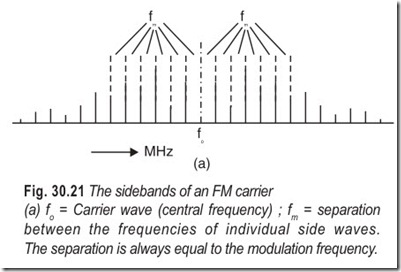
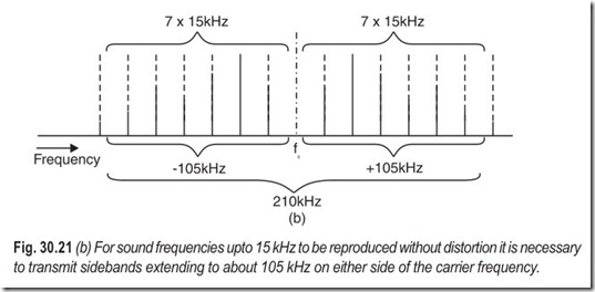
The sidebands arising in FM, constitute a very important problem. In FM, an infinite number of sideband frequencies arise symmetrically around the carrier frequency even when it is only a single sine wave that is modulating the carrier. The sidebands are separated by a frequency which is always equal to the modulating frequency; at first, with increasing distance from the carrier, their amplitudes vary irregularly, then they fall off regularly and rapidly, as shown in Fig. 30.21 (a). The modulating voltage consists of the sum of several sine waves. Each one of these sine waves will generate a sideband spectrum of its own. The complete frequency spectrum will be extraordinarily extensive and complex. Theoretically, all of these sidebands must reach the detector stage in the receiver, in order that they may be translated into a faithful reproduction of the original sound.
The question now arises, how many sidebands are essential for a sufficiently faithful reproduction of the original sound, and how many of them will have to reach the detector. It depends on the ratio between the modulating frequency and the frequency swing. As a thumb rule, one may say that at least first five to seven paired waves of each sideband must be transmitted. Because the frequency separating sideband waves is always equal to the modulation frequency, each group of seven sidebands will extend over a frequency band equal to seven times the modulation frequency, the two bands lying on either side of the carrier. If the modulation frequency has the highest value that has to be transmitted, i.e. 15 kHz (the highest audio frequency), the distance of both the highest and the lowest sideband frequencies from the carrier will be (7 × 15) = 105 kHz, Fig. 30.21 (b).
We conclude that the bandwidth of every link in the chain of FM transmission must be at least 200 kHz.
This is a great disadvantage in comparison with any AM system, in which only one upper and one lower
sideband wave has to be transmitted and which, for conveying the maximum audio frequency of 15 kHz; only requires a bandwidth of (2 × 15) = 30 kHz. In actual practice, the bandwidth of AM transmitters is often limited to 9 kHz, making the highest audio frequency transmissible 4.5 kHz.
In consequence of the great bandwidth they require, FM systems can only be employed in very high frequency (VHF) ranges, in which a broad frequency band can be allocated to each transmitter without danger of its breaking into the sideband of some other transmitter. It is impossible to do this in the long, medium or short wave bands; it may become possible in the VHF range, that is, with wavelengths under 10 metres and frequencies over 30 MHz.
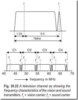
A sound signal is broadcast at the same time as the picture signal; silent television has never existed. The information in the sound signal is quite separate and different from that of the picture signal. The simplest course is to convey it by means of a second carrier wave, and have it in the same frequency range as the picture carrier; and as close to it as possible. The reasons for doing so are to make it possible for a single receiving aerial to take up both picture and sound systems efficiently and to enable both signals to be amplified together, at least in the earlier stages of the receiver. The sound carrier frequency is, therefore, given a frequency such that it lies just far enough above the highest picture sideband frequency, to ensure that the much narrower sidebands of the sound carrier do not interfere with the picture sideband. A separation of about 1 MHz is sufficient to avoid such interference. A 625 line television channel showing the pass bands of the vision and sound transmitters is shown in Fig.30.22. The term sound channel is frequently used for the narrow frequency band taken up by the sound transmitter within the television channel.
MONOCHROME TV CAMERA
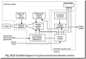
Simplified diagram of a typical monochrome television camera is given in Fig. 30.23. An optical system focuses light reflected from the scene onto the face plate of the camera tube. Aphotoelectric process transforms the light image into a virtual electronic replica in which each picture element is represented by a voltage. A scanning beam in the pick-up tube next converts the picture, element by element, into electrical impulses. At the output an electrical sequence developes that represents the original scene. The output of the camera tube is then amplified to provide the video signal for the transmitter. A sample of the video signal is also provided for observation in a CRT viewfinder mounted on the camera housing.
Electronic circuits that provide the necessary control synchronisation and power supply voltages operate the TV camera tube. A deflection system is included in the TV camera to control the movement of the camera tube scanning beam. Many TV cameras receive synchronising pulses from a studio control unit. This unit also provides the sync pulses that synchronises the receiver with the camera.
Some TV cameras however generate their own control signals. In turn, they provide output pulses to synchronise the control unit. Manual controls are also provided at the rear of the camera for setting the optical lens and for zooming. Because of the complex electronic circuits and controls, early TV cameras were rather large and awkward to handle. Recent innovations have revolutionised the cameras’ construction.
CAMERA TUBE CHARACTERISTICS
One important characteristic of all camera tubes is their light transfer characteristic. This is the ratio of the face plate illumination in foot candles to the output signal current in nanoamperes (nA). This characteristic may be considered as a measure of the efficiency of a camera tube. Typical values of output current range from 200 nA to 400 nA.
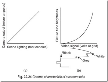
The term gamma, in a television system, is applied to camera tubes and to picture tubes. Gamma is a number which expresses the compression or expansion of original light values. Such variations, if present, are inherent in the operation of the camera tube or picture tube.
With camera tubes the gamma value is generally 1. This value represents a linear characteristic that does not change the light values from the original scene when they are translated into electronic impulses, see Fig. 30.24(a). However, the situation is different in the case of picture tubes which have gamma of approximately 3. The number varies slightly for different types of picture tubes and also for different manufacturers. For picture tubes it is desirable to provide improved contrast. Emphasising the bright values to a greater degree than the darker values accomplishes this. Fig. 30.24(b) is a typical picture tube gamma characteristic. Note that the bright portions of the signal operate on the steepest portion of the gamma curve. Conversely, the darker signal portions operate on a lesser slope. Thus it can be seen that the bright picture portions will be emphasised to a greater degree than the darker picture portions.
For proper colour reproduction the spectral response of a camera tube is an important parameter. As nearly as possible the tube should have the same spectral response as the human eye. This is necessary to render colours in their proper tones. It is also important in reproducing black and white pictures, thereby producing the proper grey scale. Tubes designed to operate in a colour camera have a greater response to each of the primary colours. Today, spectral response distribution has made possible the manufacture of camera tubes that are sensitive to the infrared, the ultraviolet and even the X-rays. But variations in spectral response have had little effect on the other operating characteristics of the tube.
If the photosensitive material in a camera tube was able to emit an electron for each photon of light focused upon the material, the quantum efficiency of the material would be 100 per cent. The formula for quantum efficiency is :
A quantum efficiency of 100% is almost impossible. However quantum efficiency is a practical way to compare photosensitive surfaces in a camera tube. In this comparison, photocurrent per lumen is measured using a standard light source. A lumen is the amount of light that produces an illumination of one foot candle over an area of one square foot. The source adopted for measurement is a tungsten-filament light operating at a colour temperature of 2870°K. Since the lumen is actually a measure of brightness stimulation to the human eye, quantum efficiency is a convenient way to express the sensitivity of the image pick-up tube.
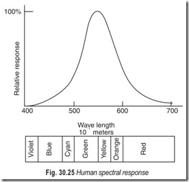
Our eyes operate as a frequency-selective receiver that peaks in the yellow-green region at a wavelength of about 560 nanometres (560 × 10–9 metres) as shown in Fig. 30.25. Spectral response of vidicon type 7262A is illustrated in Fig. 30.26.
The term lag refers to the time lag during which the image on the camera tube decays to an innoticeable value. All camera tubes have a tendency to retain images for short periods after the image is removed. Some types do it more than others. Lag on a television picture causes smear (comet tails) to appear following rapidly moving objects.
Lag may be expressed as a percentage of the initial value of the signal current remaining 1/20s after the illumination is removed. Typical lag values for vidicon range from 1.5% to 5%. Plumbicons have
lag values as low as 1.5%.
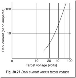
Dark current refers to the current that flows through the device even in total darkness. It is a form of semiconductor leakage current. Dark current forms the floor of the video signal or black level. Variations in temperature, therefore, alter the black level and electronic processing is required to maintain a constant black level. Automatic black level circuits clamp the black level to the setup level of the video signal.
Dark current also varies with applied target voltage in vidicons. One of the factors that lowers sensitivity is the recombination of electrons and holes where both cease to act as current carriers. By increasing the voltage field gradient in the target the likelihood of recombination decreases and more of the carriers liberated by light reach the target surfaces.
Sensitivity also varies with dark current and, therefore target voltage. Sensitivity rises for higher values of dark current. Dark current is adjusted to particular values by adjusting the target voltage. This means that sensitivity varies somewhat with the target voltage and a very simple automatic sensitivity control can be set up which resets target voltage as a function of output signal current.
Typical characteristics of vidicon camera tube are given in the Table 30.1.
VIDICON CAMERA TUBE
Vidicon is a simple, compact TV camera tube that is widely used in education, medicine, industry, aerospace and oceanography. It is, perhaps, the most popular camera tube in television industry. During the past several years, much effort has been spent in developing new photoconductive materials for use in its internal construction. Today with these new materials, some vidicons can operate in exposure to direct sunlight or in near total darkness. Also, these tubes are available in diameters ranging from ½ to 4½ inches, and some of the larger ones even incorporate multiplier sections similar to those in the image orthicon. The main difference between the vidicon and the image orthicon is physical size and the photosensitive material that converts incident light rays into electrons.
The image orthicon depends on the principle of photoemission wherein electrons are emitted by a substance when it is exposed to light. The vidicon, on the other hand employs photoconductivity, that is, a substance is used for the target whose resistance shows a marked decrease when exposed to light.
In Fig. 30.28 the target consists of a transparent conducting film (the signal electrode) on the inner surface of the face plate and a thin photoconductive layer deposited on the film. Each cross sectional element of the photoconductive layer is an insulator in the dark but becomes slightly conductive where it is illuminated. Such an element acts like a leaky capacitor having one plate at the positive potential of the signal electrode and the other one floating. When the light from the scene being televised is focused onto the surface of the photoconductive layer, next to the face plate, each illuminated element conducts slightly the current depending on the amount of light reaching the element.
This causes the potential of the opposite surface (towards the gun side) to rise towards the signal electrode potential. Hence, there appears on the gun side of the entire layer surface a positive-potential replica of the scene composed of various element potential corresponding to the pattern of light which is focused onto the photoconductive layer.
When the gun side of the photoconductive layer, with its positive potential replica, is scanned by the electron beam, electrons are deposited from the beam until the surface potential is reduced to that of the cathode in the gun. This action produces a change in the difference of potential between the two surfaces of the element being scanned. When the two surfaces of the element which form a charged capacitor are connected through the signal electrode circuit and a scanning beam, a current is produced which constitutes the video signal. The amount of current flow is proportional to the surface potential of the element being scanned and to the rate of the scan. The video signal current is then used to develop a signal-output voltage across the load resistor. The signal polarity is such that for highlights in the image, the input to the first video amplifier swings in the negative direction. In the interval between scans, whenever the photoconductive layer is exposed to light, migration of charge through the layer causes its surface potential to rise towards that of the signal plate. On the next scan, sufficient electrons are deposited by the beam to return the surface to the cathode potential.
The electron gun contains a cathode, a control gird (grid no. 1) and an accelerating grid (grid no. 2). The beam is focused on the surface of the photoconductive layer by the combined action of the uniform magnetic field of an external coil and the electrostatic field of grid no. 3. Grid no. 4 serves to provide a uniform decelerating field between itself and the photoconductive layer, so that the electron beam will tend to approach the layer in a direction perpendicular to it, a condition that is necessary for driving the surface to cathode potential. The beam electrons approach the layer at a low velocity because of the low operating voltage of the signal electrode. Deflection of the beam across the photoconductive substance is obtained by external coils placed within the focusing field.
Fig. 30.31 shows the base diagram for a typical vidicon. All connections except that made to the target ring are made at the base. In this case, there are places for eight pins equally spaced around the sealed exhaust tip. A short or missing pin serves as the indexing system for socket connections. In most cases, the tube must be oriented in a particular way for optimum performance.
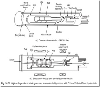
Some vidicons made especially for portable cameras achieve beam focus by electrostatic means alone, Fig. 30.32. These employ several focus elements and use higher accelerating voltages.
Electrostatic lenses achieve a savings in electrical power in several ways. First, the current needed for magnetic focus coils is eliminated, as well as the power consumed by the series regulators that control focus current. Next, because the focus coil is eliminated, the space it occupies in the yoke assembly is eliminated. Magnetic reluctance in the gap between deflection coil poles is thereby reduced and less power is needed for deflection.
MONOCHROME PICTURE TUBE
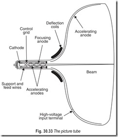
The cathode ray tube or CRT—as the picture tube is commonly known as (shown in Fig. 30.33) is a large glass structure from which as much air has been evacuated as possible.
At the narrow end (the neck) of the tube is an assembly known as the electron gun. This comprises the elements which emit and control the electron beam just as a machine gun shoots and controls the direction of a stream of bullets.
The wide end (or the face) of the tube may be round or rectangular in shape. A thin coating or fluorescent material called a phosphor is deposited on the inside surface of the face. When a high speed beam, fired from the electron gun, strikes the phosphor, the face of the tube shows a tiny spot of light at the point where it strikes. Thus, the screen converts the energy of moving electrons into light energy.
All early television picture tubes had round screens. Since the TV picture is transmitted as a rectangle having an aspect ratio 4:3, there was much wasted space, or much wasted picture, if an attempt was made to use the entire tube screen-width. Virtually all modern receivers utilise rectangular-faced tubes.
Electrons are liberated from the filament or cathode of an ordinary vacuum tube. It is this stream of electrons that constitutes the plate current of the tube. Electrons released in exactly the same manner in the cathode ray tube form the television picture. The cathode of electron emitter is a small metal cylinder which is covered by an oxide coating. When the cathode is heated to a dull red by a heater wire located inside the cathode mounting, electrons are emitted by the cathode in large quantities. The electrons emitted by the cathode of an ordinary tube move in all directions while those coming from the cathode of the cathode ray tube are emitted in a specific forward direction.
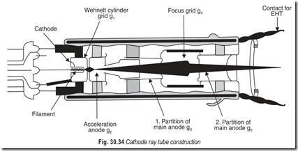
The element that governs the intensity of the electron beam moving through the picture tube is the control grid. Unlike its counterpart in the common vacuum tube, it is cylindrical in shape and resembles a metal cap rather than a wire screen. This metal cap is called Wehnelt cylinder, Fig. 30.34. The front of the Wehnelt cylinder contains a small opening or aperture which acts as an outlet for the electron beam. This arrangement is necessary to achieve a thin electron beam.
Most picture tubes have a second cylindrical structure, placed adjacent to the control grid, as can be seen in Fig. 30.34. The principal function of the first anode is that of accelerating the electrons that emerge from the pinhole in the control grid structure. This accelerating action also causes some degree of beam forming, since the electrons are caused to increase speed as they pass through the apertures in the first anode. The potential applied to the first anode is in the vicinity of 250 to 450 volts. The position of this element is such that it causes the electrons coming from the grid to accelerate as a result of the electrostatic force of attraction between the negatively charged electrons and its positive potential.
Some picture tubes do not have a first anode or accelerating grid, as it is more appropriately called. In those tubes, acceleration is accomplished by high voltages applied to the second anode. The first anode initiates the forming of the electron beam because the positive charge on it draws electrons from the cathode. But, because we want the electron beam to hit the phosphor screen, we need another anode located closer to the screen. A second positive anode is added to the electron gun structure. This element usually carries anywhere from 8,000 volts to 20,000 volts (positive) depending on the type of picture tube.
The second anode may consist of two distinct parts : (1) a cylindrical metallic structure adjacent to and following the first anode, and (2) a conductive coating inside the glass envelope which covers almost the entire area of the glass bell.
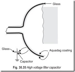
The conductive coating which forms a large part of the second anode is colloidal graphite deposit called aquadag. In addition to its accelerating action, the aquadag coating plays an important part in maintaining a thin electron beam, and assists in filtering the ripple from the high-voltage supply.
The glass picture tube sometimes has an inner conductive coating which forms part of the second anode and an outer coating of the same material that covers about the same area on the glass surface. This electrical sandwich consisting of a nonconductor—the glass envelope—separating two conducting layers, forms a capacitor. Although its capacitance is not very high (approximately 500 pf), it is large enough to serve as a filter-capacitor for the high voltage supply. The aquadag coating is connected to the chassis (ground) of the receiver as illustrated in Fig. 30.35. The inner coating is joined to the second anode and is connected to the high voltage terminal inside the receiver. Thus, this capacitor is connected across the high-voltage supply which provides the potential needed for the second anode.
TELEVISION AS A SYSTEM
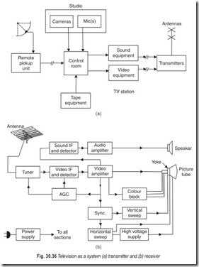
As shown in Fig. 30.36, television operates as a system, the station, and the numerous receivers within range of its signals. The station produces two kinds of signals, video originating from the camera or tape recording, and sound from a microphone or other source. Each of the two signals is generated, processed, transmitted separately, video as an amplitude-modulated signal, and sound as a frequency-modulated signal.
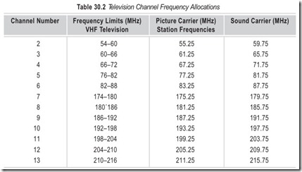
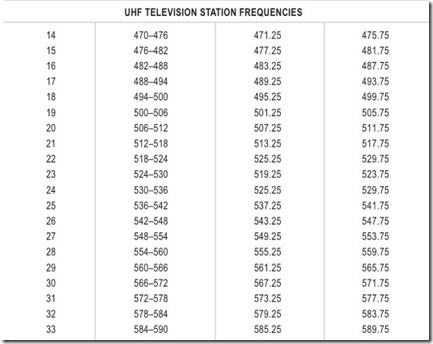
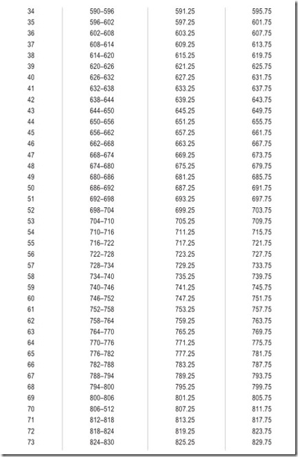
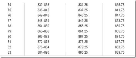
Considering such things as distance between stations, radiated power, geographic location, and topography, each station is assigned a particular channel to reduce the possibility of inter-channel interference. A station may operate in either of two bands. VHF (very high frequency) channels 2 through 13, extending from 54 to 216 MHz, or UHF (ultra high frequency) channels 14 through 83, extending from 470 to 890 MHz. Each channel occupies a very wide bandpass which can best be appreciated by realising that nearly seven radio broadcast bands would be required to accommodate even one TV station. The frequency allocations are in numerical sequence except for a couple of gaps where frequencies were previously assigned to other services.
AMERICAN 525-LINE TV SYSTEM
The transmitted television signal must comply with strict standards established by the Federal Communication Commission. The standards ensure that uniformly high quality monochrome and colour picture and sound will be transmitted. Standards are also required so that television receiver can be designed to receive these standard signals and thus provide a correct reproduction of the original picture and sound.
The details of the FCC standard are:
1. Each VHF and UHF television station is assigned a channel that is 6 MHz wide. The composite video signal must fit into the 6 MHz bandwidth. The composite signal includes the video carrier, one vestigial sideband for the video signal, one complete sideband for the video signal, the colour signals, the synchronising and blanking pulses, and the FM sound signal.
2. The visual (picture) carrier frequency is 1.25 MHz above the low end of each channel.
3. The aural (sound) carrier frequency is 4.5 MHz above the visual carrier frequency.
4. The chrominance (colour) subcarrier frequency is 3.579545 MHz above the picture carrier frequency.
For practical purposes, the subcarrier frequency is expressed as 3.58 MHz.
5. One complete picture frame consists of 525 scanning lines (483 active lines actually produce the picture. The remaining lines are blanked out during the vertical retrace). There are 30 frames per second.
6. Each frame is divided into two fields; thus there are 60 fields per second. Each field contains 262½ lines, interlaced with the preceding field.
7. The scene is scanned from left to right horizontally at uniform velocity progressing downward with each additional scanning line. The scene is retraced rapidly (blanked out) from the bottom to the top, at the end of each field.
8. The aspect ratio of the picture is four units horizontally to three units vertically.
9. At the transmitter the equipment is so arranged that a decrease in picture light intensity during scanning causes an increase in radiated power. This is known as negative picture transmission.
10. The video part of the composite signal is amplitude modulated. The synchronising and blanking pulses are also transmitted by amplitude modulation and these pulses are added to the composite video signal.
11. The colour signal is transmitted as a pair of amplitude modulation sidebands. These sidebands effectively combine to produce a chrominance signal varying in hue or tint (phase angle of the signal) and saturation (colour vividness). Saturation corresponds to the amplitude of the colour signal. Colour information is transmitted by interleaving the colour signal frequencies between spaces in the monochrome video signals.
12. The sound signal is frequency modulated. As in FM broadcast systems the sound signal may also be produced by indirect FM method. The maximum deviation of TV is + 25 kHz.
13. Table 30.2 shows the frequencies assigned to the United States VHF and UHF channels.
According to FCC rules and regulations, line 19 of the vertical blanking interval of each field is reserved for a special signal. This is the vertical interval reference (VIR) signal. The VIR signal is known as the chrominance reference. While originally intended for station use, it is also utilised by television receivers. At the station, the VIR signal is used as a reference to assure the correct transmitted hue and saturation of the colour signal. At the receiver, the signal and automatic circuits help to provide accurate colour reproduction. When this method is used, it eliminates the need for manual colour control adjustment.
THE 625-LINE SYSTEM
The CCIR-B standard is adopted by our country. The details of the CCIR-B standard are:
1. Each VHF and UHF television station is assigned a channel that is 7 MHz wide. The composite video signal must fit into the 7 MHz bandwidth.
2. The visual (picture) carrier frequency is 1.25 MHz above the low end of each channel.
3. The aural (sound) carrier frequency is 5.5 MHz above the visual carrier frequency.
4. The chrominance (colour) subcarrier frequency is 4.43361875 MHz above the picture carrier frequency. For practical purposes, the subcarrier frequency is expressed as 4.43 MHz.
5. One complete picture frame consists of 625 scanning lines (585 active lines actually produce the picture. The remaining lines are blanked out during the vertical retrace). There are 25 frames per second.
6. Each frame is divided into two fields; thus, there are 50 fields per second. Each field contains 312½ lines, interlaced with the preceding field.
7. The scene is scanned from left to right horizontally at uniform velocity, progressing downward with each additional scanning line. The scene is retraced rapidly (blanked out) from the bottom to the top, at the end of each field.
8. The aspect ratio of the picture is four units horizontally to three units vertically.
9. At the transmitter, the equipment is so arranged that a decrease in picture light intensity during scanning causes an increase in radiated power. This is knwon as negative picture transmission.
10. The video part of the composite signal is amplitude mlodulated. The synchronising and blanking pulses are also transmitted by amplitude modulation and these pulses are added to the composite video signal.
11. The colour signal is transmitted as a pair of amplitude modulation sidebands. These sidebands effectively combine to produce a chrominance signal varying in hue and tint (phase angle of the signal) and saturation (colour vividness). Saturation corresponds to the amplitude of the colour signal. Colour information is transmitted by interleaving the colour signal frequencies between spaces in the monochrome video signal.
12. The sound signal is frequency modulated. As in FM broadcast systems, the sound signal may also be produced by indirect FM method. The maximum deviation of TV is + 25 kHz.
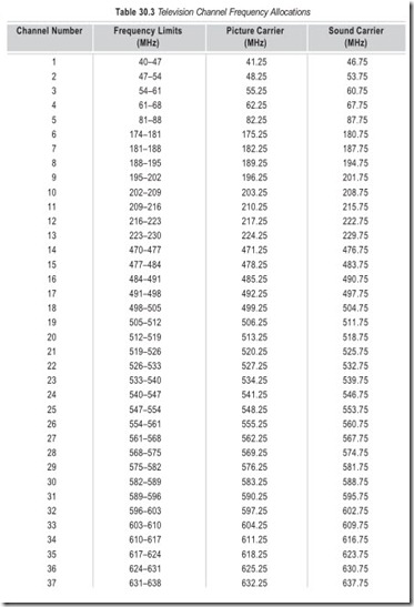
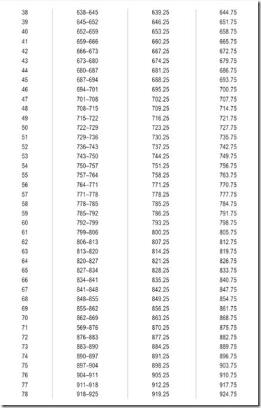
13. Table 30.3 shows the frequencies assigned to the VHF and UHF channels in India.
VESTIGIAL SIDEBAND TRANSMISSION
Because of the extensive bandwidth requirements of the video signal, it is desirable to make use of a bandwidth saving technique. The signal information is fully contained in each of the two sidebands of the modulated carrier; and provided the carrier is present, one sideband may be suppressed altogether. The single sideband transmission technique can reduce the bandwidth requirement to half, viz. 5 MHz. However, it is not possible to do this in the case of a television signal because a television signal also contains very low frequencies including even the dc information. It is impossible to design a filter which will cut off the unwanted band while passing the carrier frequencies and low-frequency components of the other sideband, without objectionable phase distortion.
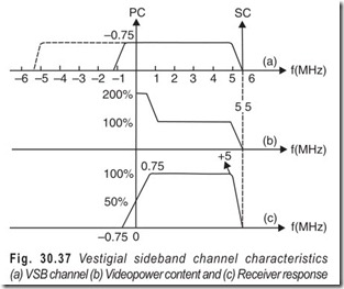
As a compromise, a part of only one sideband is suppressed. The transmitted signal consists of one complete sideband together with the carrier, and a vestige of the partially suppressed sideband as shown in Fig. 30.37. In the vestigial sideband transmission system, there is a saving in the bandwidth required, and the filtering required is not so difficult to achieve.
EXERCISES
Descriptive Questions
1. What are the elements of a television system?
2. Explain the significance of scanning.
3. What are the different scanning methods?
4. Differentiate between linear scanning, sequential scanning and interlaced scanning.
5. Define the following terms: (a) Frame (b) Critical flicker frequency (c) Odd and even field (d) Trace and retrace (e) Active and inactive lines (f) Aspect ratio (g) Kell factor (h) Flicker (i) Vertical resolution
(j) Horizontal resolution (k) Picture element (l) Video bandwidth (m) Test Card (n) Negative video polarity (o) Gamma.
6. What are the constituents of composite video signal?
7. Explain the working of a monochrome video camera with the help of a simplified diagram.
8. What are the characteristics of a camera tube?
9. Explain the working of a vidicon camera tube.
10. What is the difference between a camera tube and a picture tube?
11. With the help of a suitable sketch, explain the working of a picture tube.
12. Compare the 525 line American system with CCIR-B system. Which system is adopted in our country ?
Multiple Choice Questions
1. In the case of transmission of picture and sound (television) the fundamental problem is that of converting
(a) time variation into electrical information
(b) space variations into electrical information
(c) time and space variation into electrical information
2. Scanning may be defined as the process which permits the conversion of information expressed in
(a) space coordinates into time variations
(b) space and time coordinates into time variations only
(c) time coordinates into time variations
3. Aspect ratios of 4:3 are
(a) most pleasing to the eye (b) least pleasing to the eye
(b) most fatiguing to the eye (d) least fatiguing to the eye
4. Most practical television systems resort to
(a) linear scanning (b) circular scanning
(c) nonlinear scanning
5. It is common practice to scan the image from
(a) left to right (b) right to left
(c) top to bottom (d) bottom to top
6. Most scenes have brightness gradations in a
(a) vertical direction (b) horizontal direction
(c) diagonal direction
7. The resolving capability of the human eye is about
(a) half-a-minute of visual angle
(b) one minute of visual angle
(c) one and a half minute of visual angle
(d) two minutes of visual angle
8. The television picture is traced by
(a) a spot of light (b) a beam of light
9. Precision is essential in television but it is in the
(a) transmitting equipment and not receiving equipment
(b) receiving equipment and not transmitting equipment
10. The composite video signal locks in the frequency and the phase of
(a) frame oscillator (b) line oscillator
(c) frame and line oscillators
11. The highest video frequency of a system depends on the
(a) number of lines (b) rate of scanning
(c) both (a) and (b)
12. In the 625-line system, the sound carrier is
(a) amplitude modulated (b) frequency modlulated
13. In the 625-line system the picture carrier is
(a) amplitude modulated (b) frequency modulated
14. Transmitters in the centimetre wave range work almost exclusively on
(a) amplitude modulation (b) frequency modulation
Fill in the Blanks
1. Scanning may be defined as the process which permits the conversion of information expressed in…………………………………. and………………………………….coordinates into time variations only.
2. The detail which can be reproduced depends on the………………………………….of coverage by the scanning beam.
3. The process of scanning makes possible the use of a………………………………….transmission channel.
4. A varying scanning velocity for the pick-up and reproducing devices results in output for………………………………….scene brightness.
5. It is common practice to scan the image from………………………………….to…………………………………..
6. The repetition rate of flashes at and above which the flicker effect …………………………………. is called the critical flicker frequency.
7. The total number of pixels activated on the screen………………………………….the picture.
8. There is a degradation in vertical resolution due to………………………………….beam size.
9. The horizontal fly back interval occupies………………………………….of the line period.
10. The vertical flyback interval occupies………………………………….of the frame period
11. The vertical resolution of a system depends on the total number of………………………………….scanning lines.
12. The time during which the spot travels back to the top of the screen is called …………………………………. period.
13. The method of scanning, where the odd lines and even lines are alternately scanned is called …………………………………. scanning.
14. In television, the odd-line field and the even-line field make one…………………………………..
15. The voltage representation of every line scanned is separated from the next by…………………………………..
16. Each amplifying stage………………………………….the direction of video signal.
17. The video, sound, and control signals combine to make up………………………………….video signal.
18. The lowest frequency officially allocated to television by international agreement is…………………………………..
19. The maximum deviation laid down for television sound is…………………………………..
20. At least first………………………………….to………………………………….paired waves of each sideband must be transmitted.
21. The bandwidth of every link in the chain of FM transmission must be at least…………………………………..
22. The ratio of the face plate illumination in foot candles to the output signal current in nanoamperes is called the………………………………….characteristic.
23. With camera tubes, the gamma value is generally…………………………………..
24. With picture tubes, the gamma value is generally…………………………………..
25. As nearly as possible, the camera tube should have the same spectral response as the…………………………………..
26. The formula for quantum efficiency is…………………………………..
27. Quantum efficiency is a conveninet way to express the………………………………….of the image picture tube.
28. Lag on a television picture causes………………………………….to appear following rapidly moving objects.
29. Dark current refers to the current that flows through the device even when in total…………………………………..
30. A short or missing pin in the base serves as the………………………………….system for socket connections.
31. All electrostatic lenses achieve a saving in………………………………….in several ways.
ANSWERS
Multiple Choice Questions
|
1. (c) |
2. (b) |
3. (a) & (d) |
4. (a) |
5. (a) & (c) |
6. (a) |
|
7. (a) |
8. (b) |
9. (a) |
10. (c) |
11. (a) |
12. (b) |
|
13. (a) |
14. (a) |
Fill in the Blanks1. space, time |
2. |
completeness |
3. |
single |
|
4. varying, constant |
5. |
left, right |
6. |
disappears |
|
7. reproduce |
8. |
finite |
9. |
17% |
|
10. 6% |
11. |
active |
12. |
vertical retrace |
|
13. interlaced |
14. |
frame |
15. |
blanking interval |
|
16. inverts |
17. |
composite |
18. |
40 Mhz |
|
19. ± 25 kHz |
20. |
five, seven |
21. |
200 kHz |
|
22. transfer |
23. |
1 |
24. |
3 |
|
25. human eye |
26. |
Qeff = electrons/photons |
27. |
sensitivity |
|
28. smear |
29. |
darkness |
30. |
indexing |
|
31. electrical power |


