INDUSTRIAL OPTICAL SENSORS
Optical sensors are devices that are used to measure temperature, pressure, strain, vibration, acoustics, rotation, acceleration, position, and water vapor content. The detector of an optical sensor measures changes in characteristics of light, such as intensity, polarization, time of flight, frequency (color), modal cross-talk or phase.
Optical sensors can be categorized as point sensors, integrated sensors, multiplexed sensors, and distributed sensors. This section specifies the three that are typically applied in industrial control systems; color sensors, light section sensors and scan sensors.
3.1.1 Color sensors
Color sensors that can operate in real time under various environmental conditions benefit many applications, including quality control, chemical sensing, food production, medical diagnostics, energy conservation, and monitoring of hazardous waste. Analogous applications can also be found in other fields of the economy; for example, in the electric industry for recognition and assignment of colored cords, and for the automatic testing of mounted LED (light-emitting diode) arrays or matrices, in the textile industry to check coloring processes, or in the building materials industry to control com- pounding processes.
Such sensors are generally advisable wherever color structures, color processes, color nuances, or colored body rims must be recognized in homogeneously continuous processes over a long period, and where color has an influence on the process control or quality protection.
(1) Operating principle
Color detection occurs in color sensors according to the three-field (red, green, and blue) proce- dure. Color sensors cast light on the objects to be tested, then calculate the chromaticity coordi- nates from the reflected or transmitted radiation, and compare them with previously stored reference tristimulus (red, green, and blue) values. If the tristimulus values are within the set tolerance range, a switching output is activated. Color sensors can detect the color of opaque objects through reflection (incident light), and of transparent materials via transmitted light, if a reflector is mounted opposite the sensor.
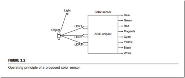
In Figure 3.2, the color sensor shown can sense eight colors: red, green, and blue (primary colors of light); magenta, yellow, and cyan (secondary colors); and black and white. The ASIC chipset of the color sensor is based on the fundamentals of optics and digital electronics. The object whose color is to be detected is placed in front of the system. Light reflected from the object will fall on the three convex lenses that are fixed in front of the three LDRs (light dependent resistors). The convex lenses will cause the incident light rays to converge. Red, green, and blue glass filters are fixed in front of LDR1, LDR2, and LDR3, respectively. When reflected light rays from the object fall on the gadget, the filter glass plates determine which of these three LDRs will be triggered. When a primary color falls on the system, the lens corresponding to that primary color will allow the light to pass through; but the other two glass plates will not allow any transmission. Thus, only one LDR will be triggered and the gate output corresponding to that LDR will indicate which color it is. Similarly, when a secondary color light ray falls on the system, the two lenses corresponding to the two primary colors that form the secondary color will allow that light to pass through while the remaining one will not allow any light ray to pass through it. As a result two of these three LDRs are triggered and the gate output corresponding to these indicates which color it is. All three LDRs are triggered for white light and none will be triggered for black, respectively.
(2) Basic types
Color sensors can be divided into three-field color sensors and structured color sensors according to how they work.
(a) Three-field color sensors
This sensor works based on the tristimulus (standard spectral) value function, and identifies colors with extremely high precision, 10,000 times faster than the human eye. It provides a compact and dynamic technical solution for general color detection and color measurement. It is capable of detecting, analyzing, and measuring minute differences in color, for example, as part of LED testing, calibration of monitors, or where mobile equipment is employed for color measurement. Based on the techniques used, there are two kinds of three-field color sensors:
(i) The three-element color sensor. This sensor includes special filters so that their output currents are proportional to the function of standard XYZ tristimulus values. The resulting absolute XYZ standard spectral values can thus be used for further conversion into a selectable color space. This allows for a sufficiently broad range of accuracies in color detection from “eye accurate” to “true color”, that is, standard-compliant colorimetry to match the various application environments.
(ii) The integral color sensor. This kind of sensor accommodates integrative features including (1) detection of color changes; (2) recognition of color labels; (3) sorting colored objects; (4) checking of color-sensitive production processes; and (5) control of the product appearance.
(b) Structured color sensors
Structured color sensors are used for the simultaneous recording of color and geometric information, including (1) determination of color edges or structures and (2) checking of industrial mixing and separation processes. There are two kinds of structured color sensors available:
(i) The row color sensor. This has been developed for detecting and controlling color codes and color sequences in the continuous measurement of moving objects. These color sensors are designed as PIN- photo-diode arrays. The photo diodes are arranged in the form of honeycombs for each of three rhombi. The diode lines consist of two honeycomb lines displaced a half-line relative to each other. As a result, it is possible to implement a high resolution of photo diode arrays in the most compact format. In this case, the detail to be controlled is determined by the choice of focusing optics.
(ii) The hexagonal color sensor. This kind of sensor generates information for the subsequent electronics about the three-field chrominance signal (intensity of the three-receiving segments covered with the spectral filters), as well as about the structure and the position.
(3) Application guide
In industrial control, color sensors are selected by means of the application-oriented principle, referring to the following technical factors; (1) operating voltage, (2) rated voltage, (3) output voltage,
(4) residual ripple maximum, (5) no-load current, (6) spectral sensitivity, (7) size of measuring dot minimum, (8) limiting frequency, (9) color temperature, (10) light spot minimum, (11) permitted ambient temperature, (12) enclosure rating, (13) control interface type.
Light section sensors
Light section methods have been utilized as a three-dimensional measurement technique for many years, as non-contact geometry and contour control. The light section sensor is primarily used for automating industrial production processes, and testing procedures in which system-relevant posi- tioning parameters are generated from profile information. Two-dimensional height information can be collected by means of laser light, the light section method, and a high resolution of receiver array. Height profiles can be monitored, the filling level detected, magazines counted, or the presence of objects checked.
(1) Operating principle
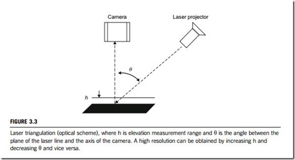
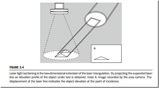
A light section is obtained using the laser light section method. This is a three-dimensional procedure to measure object profiles in a one-sectional plane. The principle of laser triangulation (see Figure 3.3) requires a camera positioned orthogonal to the object’s surface area, to measure the lateral dis- placement, or deformation, of a laser line projected at an angle q onto the object’s surface (see
Figure 3.4). The elevation profile of interest is calculated from the deviation of the laser line from the zero position.
A light section sensor consists of a camera and a laser projector, also called a laser line generator. The measurement principle of a light section sensor is based on active triangulation (Figure 3.3). The simplest method is to scan a scene by a laser beam and detect the location of the reflected beam. A laser
beam can be spread by passing it through a cylindrical lens, which results in a plane of light. The profile of this light can be measured in the camera image, thus giving triangulation along one profile. In order to generate dense range images, one has to project several light planes (Figure 3.4). This can be achieved either by moving the projecting device, or by projecting many strips at once. In the latter case the strips have to be encoded; this is referred to as the coded-light approach. The simplest encoding is achieved by assigning different brightnesses to every projection direction, for example, by projecting a linear intensity ramp.
Measuring range and resolution are determined by the triangulation angle between the plane of the laser line and the optical axis of the camera (see Figure 3.3). The more obtuse this angle, the larger is the observed lateral displacement of the line. The measured resolution is increased, but the measured elevation range is reduced. Criteria related to an object’s surface characteristics, camera aperture or depth of focus, and the width of the laser line can reduce the achievable resolution.
(2) Application guide
In applications, there are some technical details of the laser light section method that require particular attention.
(a) Object surface characteristics
One requirement for the utilization of the laser light section method is an at least partially diffuse reflecting surface. An ideal mirror would not reflect any laser radiation into the camera lens, and the camera cannot view the actual reflecting position of the laser light on the object surface. With a completely diffuse reflecting surface, the angular distribution of the reflected radiation is indepen- dent of the angle of incidence of the incoming radiation as it hits the object under test (Figure 3.4).
Real surfaces usually provide a mixture of diffuse and reflecting behavior. The diffuse reflected radiation is not distributed isotropically, which means that the more obtuse the incoming light, the smaller the amount of radiation is reflected in an orthogonal direction to the object’s surface. Using the laser light section method, the reflection characteristics of the object’s surface (depending on the submitted laser power and sensitivity of the camera) limit the achievable angle of triangulation q (Figure 3.3).
(b) Depth of focus of the camera and lens
To ensure broadly constant signal amplitude at the sensor, the depth of focus of the camera lens, as well as the depth of focus of the laser line generator have to cover the complete elevation range of measurement.
By imaging the object under test onto the camera sensor, the depth of focus of the imaging lens increases proportionally to the aperture number k, the pixel distance y, following a quadratic rela- tionship with the imaging factor @ (¼ field of view/sensor size).
The depth of focus 2z is calculated by:
2z ¼ 2yk @ ð1 þ @Þ
In the range ±z around the optimum object distance, no reduction in sharpness of the image is evident.
Example:
Pixel distance y ¼ 0.010 mm Aperture number k ¼ 8 Imaging factor @ ¼ 3
2z ¼ 2 X 0.010 X 8 X 3 X (1 þ 3) ¼ 1.92 mm
With fixed image geometry a diminishing aperture of the lens increases its depth of focus. A larger aperture number, k, cuts the signal amplitude by a factor of 2 with each aperture step; it decreases the optical resolution of the lens and increases the negative influence of speckle effect.
(c) Depth of focus of a laser line
The laser line is focused at a fixed working distance. If actual working distances diverge from the given setting, the laser line widens, and the power density of the radiation decreases.
The region around the nominal working distance, where line width does not increase by more than
a given factor, is the depth of focus of a laser line. There are two types of laser line generators: laser micro line generators and laser macro line generators.
Laser micro line generators create thin laser lines with a Gaussian intensity profile that is orthogonal to the direction of propogation laser line. The depth of focus of a laser line at wavelength L and of width B is given by the so-called Rayleigh range:
2ZR : 2ZR ¼ ðpB2Þ=ð2LÞ; where p ¼ 3:1415926
Laser macro line generators create laser lines with higher depth of focus. At the same working distance macro laser lines are wider than micro laser lines. Within the two design types, the respective line width is proportional to the working distance. Due to the theoretical connection between line width and depth of focus, the minimum line width of the laser line is limited by the application, due to the required depth of focus.
(d) Basic setback: laser speckle
Laser speckling is an interference phenomenon originating from the coherence of laser radiation; for example, the laser radiation reflected by a rough-textured surface.
Laser speckle disturbs the edge sharpness and homogeneity of laser lines. Orthogonal to the laser
line, the center of intensity is displaced stochastically. The granularity of the speckle depends on the setting of the lens aperture viewing the object.
At low apertures the speckles have a high spatial frequency; with a large k number the speckles are rather rough and particularly disturbing. Since a diffuse, and thus optically rough-textured surface is essential for using a laser light section, laser speckling cannot be entirely avoided.
Reduction is possible by (1) utilizing laser beam sources with decreased coherence length, (2) moving object and sensor relative to each other, possibly using a necessary or existing movement of the sensor or the object (e.g., the profile measurement of railroad tracks while the train is running), (3) choosing large lens apertures (small aperture numbers), as long as the requirements of depth of focus can tolerate this.
(e) Dome illuminator for diffuse illumination
This application requires control of the object outline and surface at the same time as the three-dimensional profile measurement. For this purpose, the object under test is illuminated homogeneously and diffusely by a dome illuminator. An LED ring lamp generates light that scattered by a diffuse reflecting cupola to the object of interest. In the center of the dome an opening for the camera is located, so there is no radiation falling onto the object from this direction.
Shadow and glint are largely avoided. Because the circumstances correspond approximately to the illumination on a cloudy day, this kind of illumination is also called “cloudy day illumination”.
(f) Optical engineering
The design of the system configuration is of great importance for a laser light section application high requirements, it implies the choice and dedicated optical design of such components as camera, lens, and laser line generator. Optimum picture recording within the given physical boundary conditions can be accomplished by consideration of the laws of optics. Elaborate picture preprocessing algorithms are avoided.
Measuring objects with largely diffuse reflecting surfaces by reducing or allows the use of requirements in resolution, cameras and laser line generators from an electronic mail order catalogue system testing (or for projects such as school practical, etc.).
These simple laser line generators mostly use a glass rod lens to produce a Gaussian intensity profile along the laser line (as mentioned in the operating principle section). As precision requirements increase, laser lines with largely constant intensity distribution and line width have to be utilized.
Scan sensors
Scan sensors, also called image sensors or vision sensors, are built for industrial applications. Common applications for these sensors in industrial control include alignment or guidance, assembly quality, bar or matrix code reading, biotechnology or medical, color mark or color recognition, container or product counting, edge detection, electronics or semiconductor inspection, electronics rework, flaw detection, food and beverage, gauging, scanning and dimensioning, ID detection or verification, materials analysis, noncontact profilometry, optical character recognition, parcel or baggage sorting, pattern recognition, pharmaceutical packaging, presence or absence, production and quality control, seal integrity, security and biometrics, tool and die monitoring, and website inspection.
(1) Operating principle
A scan or vision or image sensor can be thought of as an electronic input device that converts analog information from a document such as a map, a photograph, or an overlay, into an electronic image in a digital format that can be used by the computer. Scanning is the main operation of a scan, vision or image sensor, which automatically captures document features, text, and symbols as individual cells, or pixels, and so produces an electronic image.
While scanning, a bright white light strikes the image and is reflected onto the photosensitive surface of the sensor. Each pixel transfers a gray value (values given to the different shades of black in the image ranging from 0 (black) to 255 (white), that is, 256 values, to the chipset (software)). The software interprets the value in terms of 0 (black) or 1 (white) as a percentage, thereby forming a monochrome image of the scanned item. As the sensor moves forward, it scans the image in tiny strips and the sensor stores the information in a sequential fashion. The software running the scanner pieces together the information from the sensor into a digital image. This type of scanning is known as one-pass scanning.
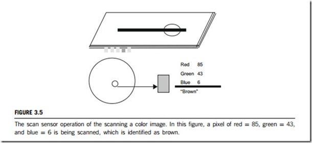
Scanning a color image is slightly different, as the sensor has to scan the same image for three different colors; red, green, and blue (RGB). Nowadays most of the color sensors perfom one-pass scanning for all three colors in one go, by using color filters. In principle, a color sensor works in the same way as a monochrome sensor, except that each color is constructed by mixing red, green, and blue as shown in Figure 3.5. A 24-bit RGB sensor represents each pixel by 24 bits of information. Usually, a sensor using these three colors (in full 24 RGB mode) can create up to 16.8 million colors.
Full width, single-line contact sensor array scanning is a new technology that has emerged, in which the document to be scanned passes under a line of chips which captures the image. In this technology, a scanned line could be considered as the cartography of the luminosity of points on the line observed by the sensor. This new technology enables the scanner to operate at previously unattainable speeds.
(2) CCD image sensors
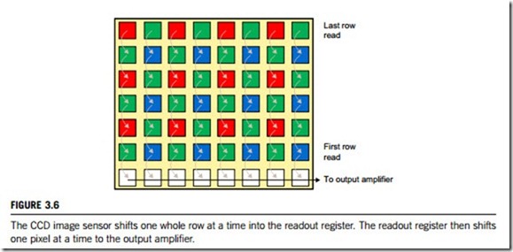
A charge-coupled device (CCD) gets its name from the way the charges on its pixels are read after an exposure. After the exposure the charges on the first row are transferred to a place on the sensor called the read-out register. From there, the signals are fed to an amplifier and then on to an analog- to-digital converter. Once the row has been read, its charges on the read-out register row are deleted, the next row enters, and all of the rows above march down one row. The charges on each row are “coupled” to those on the row above so when the first moves down, the next also moves down to fill its old space. In this way, each row can be read one at a time. Figure 3.6 is a diagram of the CCD scanning process.
(3) CMOS image sensors
A complementary metal oxide semiconductor (CMOS) typically has an electronic rolling shutter design. In a CMOS sensor the data are not passed from bucket to bucket. Instead, each bucket can be read independently to the output. This has enabled designers to build an electronic rolling slit shutter. This shutter is typically implemented by causing a reset to an entire row and then, some time later, reading the row out. The readout speed limits the speed of the wave that passes over the sensor from top
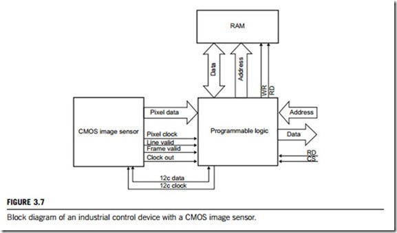
to bottom. If the readout wave is preceded by a similar wave of resets, then uniform exposure time for all rows is achieved (albeit not at the same time). With this type of electronic rolling shutter there is no need for a mechanical shutter except in certain cases. These advantages allow CMOS image sensors to be used in some of the highest specification industrial control devices or finest cameras. Figure 3.7 gives a typical architecture of industrial control devices with a CMOS image sensor.
(2) Basic types
All scan (or image or vision) sensors can be monochrome or color sensors. Monochrome sensing sensors present the image in black and white or as a grayscales. Color sensing sensors can sense the spectrum range using varying combinations of discrete colors. One common technique is sensing the red, green, and blue components (RGB) and combining them to create a wide spectrum of colors. Multiple chip colors are available on some scan (image or vision) sensors. In a widely used method, the colors are captured in multiple chips, each of them being dedicated to capturing part of the color image, such as one color, and the results are combined to generate the full color image. They typically employ color separation devices such as beam-splitters, rather than having integral filters on the sensors.
The imaging technology used in scan or image or vision sensors includes CCD, CMOS, tube, and film.
(a) CCD image sensors (charge-coupled device) are electronic devices that are capable of trans- forming a light pattern (image) into an electric charge pattern (an electronic image). The CCD consists of several individual elements that have the capability of collecting, storing, and transporting electrical charges from one element to another. This together with the photosensitive properties of silicon is used to design image sensors. Each photosensitive element will then represent a picture element (pixel). Using semiconductor technologies and design rules, structures are made that form lines or matrices of pixels. One or more output amplifiers at the edge of the chip collect the signals from the CCD. After exposing the sensor to a light pattern, a series of pulses that transfer the charge of one pixel after another to the output amplifier are applied, line after line. The output amplifier converts the charge into a voltage. External electronics then transform this output signal into a form that is suitable for monitors or frame grabbers.
CCD image sensors have extremely low noise levels and can act either as color sensors or monochrome sensors.
Choices for array type include linear array, frame transfer area array, full-frame area array, and interline transfer area array. Digital imaging optical format is a measure of the size of the imaging area. It is used to determine what size of lens is necessary, and refers to the length of the diagonal of the imaging area. Optical format choices include 1/7, 1/6, 1/5, 1/4, 1/3, 1/2, 2/3, 3/4, and 1 inch. The number of pixels and pixel size are also important. Horizontal pixels refer to the number of pixels in each row of the image sensor. Vertical pixels refer to the number of pixels in a column of the image sensor. The greater the number of pixels, the higher the resolution of the image.
Important image sensor performance specifications to consider when considering CCD image sensors include spectral response, data rate, quantum efficiency, dynamic range, and number of outputs. The spectral response is the spectral range (wavelength range) for which the detector is designed. The data rate is the speed of the data transfer process, normally expressed in megahertz.
Quantum efficiency is the ratio of photon-generated electrons that the pixel captures to the photons incident on the pixel area. This value is wavelength-dependent, so the given value for quantum efficiency is generally for the peak sensitivity wavelength of the CCD. Dynamic range is the logarithmic ratio of well depth to the readout noise in decibels: the higher the number, the better.
Common features for CCD image sensors include antiblooming and cooling. Some arrays for CCD image sensors offer an optional antiblooming gate designed to bleed off overflow from a saturated pixel. Without this feature, a bright spot which has saturated the pixels will cause a vertical streak in the resultant image. Some arrays are cooled for lower noise and higher sensitivity, so to consider an important environmental parameter operating temperature.
(b) CMOS image sensors operate at lower voltages than CCD image sensors, reducing power consumption for portable applications. In addition, CMOS image sensors are generally of much simpler design: often just a crystal and decoupling circuits. For this reason, they are easier to design with, generally smaller, and require less support circuitry.
Each CMOS active pixel sensor cell has its own buffer amplifier that can be addressed and
read individually. A commonly used design has four transistors and a photo-sensing element. The cell has a transfer gate separating the photo sensor from a capacitive floating diffusion, a reset gate between the floating diffusion and power supply, a source-follower transistor to buffer the floating diffusion from readout-line capacitance, and a row-select gate to connect the cell to the readout line. All pixels on a column connect to a common sense amplifier. In addition to, sensing in color or in monochrome, CMOS sensors are divided into two categories of output; analog or digital. Analog sensors output their encoded signal in a video format that can be fed directly to standard video equipment. Digital CMOS image sensors provide digital output, typically via a 4/ 8- or 16-bit bus. The digital signal is direct, not requiring transfer or conversion via a video capture card.
CMOS image sensors can offer many advantages over CCD image sensors. Just some of these are (1) no blooming, (2) low power consumption, ideal for battery-operated devices, (3) direct digital output (incorporates ADC and associated circuitry), (4) small size and little support circuitry, and (5) simple to design.
(c) The tube camera is an electronic device in which the image is formed on a fluorescent screen. It is then read by an electron beam in a raster scan pattern and converted to a voltage proportional to the image light intensity.
(d) Film technology exposes the image onto photosensitive film, which is then developed to play or store. The shutter, a manual door that admits light to the film, typically controls exposure.
