SELECTION AND APPLICATION
The AC induction motor-how it works
THE SQUIRREL-CAGE induction mo tor has long been the workhorse of industry because of its simplicity, rug ged construction, and low manufactur ing cost. With the increasing use of electronic adjustable-frequency con trols, the AC induction motor appears to be well positioned to maintain its leadership. To obtain the best perform ance, it is important for the user to have a good understanding of motor and control operating principles and characteristics.
The induction motor is made up of two major components-the rotor and stator. The rotor consists of a structure of steel laminations mounted on a shaft, the squirrel-cage conductors or bars, end rings, and usually a fan. The stator has a formation of steel lamina tions mounted on a frame in such a manner that slots are formed on the inside diameter of the assembly. As shown in the accompanying photo, coils of wire or bars are made up and installed in the slots. The coils are connected to form a circuit such that when energized by an AC supply volt age, a rotating magnetic field is cre ated in the stator.
This rotating magnetic field cuts through the rotor, inducing a voltage in the rotor bars, which in turn create their own magnetic field. The rotor magnetic field will attempt to line up with the stator magnetic lines of force. However, because the stator magnetic field is rotating, the rotor “chases” the stator field, never quite catching up, but following along just slightly be hind. Essentially, this is motor action. Design of the motor will dictate the specific motor characteristics, such as horsepower, torque, speed, power fac tor, and duty cycle.
Motor characteristics
A 3-phase induction motor is fur nished with three windings connected to a power source as shown in an accompanying sketch. When a poly phase alternating current flows in the
stator windmg, north and south poles are created in the stator, depending on how the windings are arranged and connected. The machine will always have at least two poles and a rotating magnetic field.
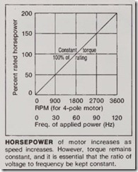
The speed (in rpm) at which the induction motor rotates is dependent on the speed of the stator rotating field and is equal to 120 X f!P, where f is the frequency of the source (Hz) and P is the number of poles. For example, a motor having two poles supplied from a 60-Hz source will run at 3600 rpm; a 4-pole motor will run at 1800 rpm. The actual speed of the motor is slightly less because of “slip.”
Slip is the difference between the speed of the magnetic field and the speed of the rotor. Slip is necessary to permit the motor action to occur. Under load, the rotor slows down and the speed adjusts itself to the point where the forces exerted by the mag netic field on the rotor are sufficient to overcome the torque requirements of the load. The resulting speed is slightly less than the stator rotating field. For example, the actual speed of a 4-pole motor will be about 1725 rpm.
The slip necessary to carry full load depends on the motor characteristics. In general, the higher the inrush cur rent, the lower the slip at which the motor can carry full load, and the high er the efficiency. The lower the inrush current, the higher will be the slip at which the motor can carry full load, and the lower will be the efficiency.
Motor supply voltages, current, torque, speed, and rotor impedance are closely related. By changing the resist ance and reactance of the rotor, the characteristics of the motor can be changed; but for any one rotor design these characteristics are fixed.
An increase in line voltage decreases the slip, while a decrease in line voltage increases the slip. In either case, sufficient current is induced in the rotor to carry the load. A decrease in line volt age has the effect of increasing the heating of the motor; an increase in line voltage decreases the heating. In other words, the motor can carry a larger load. The slip at rated load may vary from 3% to 20% for different types of motors.
The locked-rotor current and the resulting torque are the factors that determine whether the motor can be thrown across the line or whether the current has to be reduced to get the required performance. Locked-rotor currents for different-type motors will vary from 2112 to 10 times their full load current; but there are motors with even higher inrush currents.
Voltages higher than normal will increase the inrush current at a rate of about 12% for every 10% voltage increase, while the starting torque will increase at a rate of 20% for every 10% voltage increase. The reverse takes place if the voltage is lower than normal.
Torque and rotor resistance are closely related -the higher the rotor resistance, the higher the starting torque. This holds true only up to a fixed limit, beyond which a further increase in resistance causes the torque to decrease. The torque, however, is also affected by the flux in the air gap and the disposition and shape of the rotor slots and bars.
Speed-torque characteristics
Modifications in the design of the squirrel-cage motors permit a certain amount of control of the starting current and torque characteristics. These designs have been categorized by NEMA Standards into four main clas sifications.
1. Normal-torque, normal-starting current motors (NEMA Design A)
2. Normal-torque, low-starting-cur rent motors (NEMA Design B)
3. High-torque, low-starting-current, double-wound-rotor motors (NEMA Design C)
4. High-slip motors (NEMA Design D)
There are other variations, such as low-resistance motors with starting currents 8 to 10 or more times normal full-load current. These have a very high running efficiency and often find application where loads are driven con tinuously, such as on fans, milling machinery, pumps, and motor genera tors.
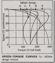
The basic NEMA types are derived from NEMA Standard MG1-1.16. The speed-torque curves for each type (NEMA Design) are shown in an accompanying drawing.
A Design A motor has a locked-rotor current that can be anywhere from 6 to 10 times full-load current. It has good running efficiency and power factor, high pullout torque, and low rated slip. The torque is about 150% at start. Pullout torque is over 200% of full-load torque.
A Design B motor has a higher reac tance than the Design A motor, obtained by means of deep, narrow rotor bars. As a result, the starting current is held to about 5 times the full-load current. This motor allows full-voltage starting in some cases where the Design A squirrel-cage motor would reqliire a reduced-voltage starter. The starting torque, slip and efficiency are nearly the same as for the Design A motor. Power factor and pullout torque are somewhat less , which may make this motor unsuitable for use where there are high load peaks. Design B is standard in 1- to 250-hp drip-proof motors and in totally enclosed, fan-cooled motors, up to approximately 100 hp.
The NEMA Design C motor has a higher starting torque than either the A orB design-about 200% of full-load torque. Breakdown torque, on the other hand, is lower than that for either the A orB design -about 180% of full-load torque.
Full-load torque is the same as that for both A and B designs. This type of motor has a “double-layer” or double squirrel-cage winding. It combines high starting torque with low starting current. Two windings are applied to the rotor, an outer winding having high resistance and low reactance and an inner winding having low resistance and high reactance. Operation is such that the reactance of both windings decrease as rotor frequency decreases and speed increases. On starting, much larger induced currents flow in the outer winding than in the inner wind ing, because at low rotor speeds the inner-winding reactance is quite high. As the rotor speed increases, the reac tance of the inner winding drops and, combined with the low inner-winding resistance, permits the major portion of the rotor current to appear in the inner winding.
The design has less current inrush than the standard type of squirrel-cage motor. The starting torque is rather high (200% and over), making this motor particularly adaptable to loads requiring high starting torque. How ever, the maximum pullout torque is lower than the starting torque, which may render this motor unsuitable where high load peaks are encountered. Typical applications are pulverizers, compressors, and conveyors.
The Design D motor produces a very high starting torque-approximately 275% of full-load torque. However, it has no true breakdown torque, as evi denced by the fact that torque decreases continuously with speed. It has low starting current, high slip, and low efficiency. Its slip is greater under load than other squirrel-cage motors and is used primarily where high start ing torque is required but the running load is light or intermittent, such as for hoists and elevators. It is also fre quently used for punch-presses and press brakes. The high slip of the motor makes the use of a flywheel very effective, since the motor speed changes with the load and allows the flywheel to store and give up energy during the operating cycle.
Induction motor current consists of reactive (magnetizing) and real (torque) components. The current com ponent that produces torque (does use ful work) is almost in phase with volt age. It results in a very high power factor that is close to 100%. The mag netizing current would be purely induc tive, except that the winding has some small resistance, and it lags the voltage by nearly 90°. It has a very low power factor, close to zero.
The magnetic field is nearly constant from no load to full load and beyond, so the magnetizing portion of the total current is approximately the same for all loads. The torque current necessary to drive the load varies with the load, increasing as the load increases. At full load, the torque current is higher than the magnetizing current; and, for a typical motor, the power factor of the resulting current is between 85% and 90%. As the load is reduced, the torque current decreases, but the magnetizing current remains about the same-so the resulting current is lower in power factor. The less the load, the lower the load current and the lower the power factor.
Low power factor at low loading occurs because the magnetizing re mains approximately the same at no load as at full load. However, a smaller magnetic field would be sufficient to provide the required torque at lower loads, and a very small magnetic field would be able to provide the small torque necessary to overcome friction at no load.


