Transmitting Digital Signals
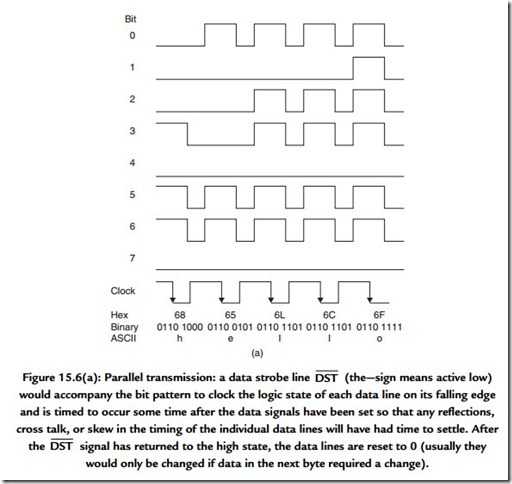
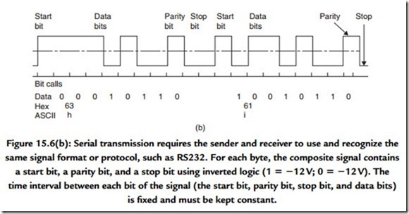
There are two ways in which you can transport bytes of information from one circuit or piece of equipment to another. Parallel transmission requires a signal line for each bit position and at least one further signal that will indicate that the byte now present on the signal lines is valid and should be accepted. Serial transmission requires that the byte be transmitted one bit at a time and in order that the receiving logic or equipment can recognize the correct beginning of each byte of information it is necessary to incorporate some form of signaling in serial data in order to indicate (as a minimum) the start of each byte. Figure 15.6 shows an example of each type.
Parallel transmission has the advantage that, where it is possible to use a number of parallel wires, the rate at which data can be sent can be very high. However, it is not easy to maintain a very high data rate on long cables using this approach and its use for digital audio is usually restricted to the internals of equipment and for external use as an interface to peripheral devices attached to a computer.
The serial link carries its own timing with it and thus it is free from errors due to skew and it clearly has benefits when the transmission medium is not copper wire but infra-red or radio. It also uses a much simpler single circuit cable and a much simpler connector. However, the data rate will be roughly 10 times that for a single line of a
parallel interface. Achieving this higher data rate requires that the sending and receiving impedances are accurately matched to the impedance of the connecting cable. Failure to do this will result in signal reflections, which in turn will result in received data being in error. This point is of practical importance because the primary means of conveying digital audio signals between equipments is by the serial AES/EBU signal interface at a data rate approximately equal to 3 Mbits per second.
You should refer to a text on the use of transmission lines for a full discussion of this point but for guidance here is a simple way of determining whether you will benefit by considering the transmission path as a transmission line.
● Look up the logic signal rise time, tR.
● Determine the propagation velocity in the chosen cable, v. This will be typically about 0.6 of the speed of light.
● Determine the length of the signal path, l.
● Calculate the propagation delay, τ = l/v.
● Calculate the ratio of tR/τ.
● If the ratio is greater than 8, then the signal path can be considered electrically short and you will need to consider the signal path’s inductance or capacitance, whichever is dominant.
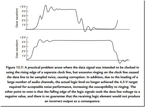
● If the ratio is less than 8, then consider the signal path in terms of a transmission line. The speed at which logic transitions take place determines the maximum rate at which information can be handled by a logic system. The rise and fall times of a logic signal are
important because of the effect on integrity. The outline of the problem is shown in Figure 15.7, which has been taken from a practical problem in which serial data were being distributed around a large digitally controlled audio mixing desk. Examples such as this illustrate the paradox that digital signals must, in fact, be considered from an analogue point of view.


