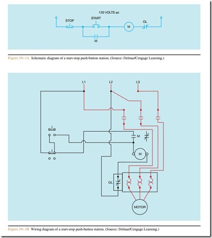
Schematic and wiring diagrams are the written language of control circuits. Maintenance electricians must be able to interpret schematic and wiring diagrams to in- stall control equipment or troubleshoot existing control circuits. Schematic diagrams are also known as line diagrams and ladder diagrams. Schematic diagrams show components in their electrical sequence without regard to physical location. Schematics are used more than any other type of diagram to connect or troubleshoot a control circuit.
Wiring diagrams show a picture of the control components with connecting wires. Wiring diagrams are sometimes used to install new control circuits, but they are seldom used for troubleshooting existing circuits. Figure 19– 1A shows a schematic diagram of a start-stop, push-button circuit. Figure 19– 1B shows a wiring diagram of the same circuit.
When reading schematic diagrams, the following rules should be remembered.
A. Read a schematic as you would a book—from top to bottom and from left to right.
B. Contact symbols are shown in their de-energized or off position.
C. When a relay is energized, all the contacts controlled by that relay change position. If a contact is shown normally open on the schematic, it will close when the coil controlling it is energized.
The three circuits shown in this and following chapters are used to illustrate how to interpret the logic of a control circuit using a schematic diagram.
Circuit #1, shown in Figure 19– 2A, is an alarm silencing circuit. The purpose of the circuit is to sound
a horn and turn on a red warning light when the pres- sure of a particular system becomes too great. After the alarm has sounded, the RESET button can be used to turn the horn off, but the red warning light must remain on until the pressure in the system drops to a safe level.
Notice that no current can flow in the system because of the open pressure switch, PS.
If the pressure rises high enough to cause pressure switch PS to close, current can flow through the normally closed S contact to the horn. Current can also flow through the red warning light. Current cannot, however, flow through the normally open RESET button or the normally open S contact (Figure 19– 2B).
If the reset button is pushed, a circuit is completed through the S relay coil. When relay coil S energizes, the normally closed S contact opens and the normally open S contact closes. When the normally closed S contact opens, the circuit to the horn is broken. This causes the horn to turn off. The normally open S con- tact is used as a holding contact to maintain current to the coil of the relay when the RESET button is re- leased (Figure 19– 2C).
The red warning light will remain turned on until the pressure switch opens again. When the pressure switch opens, the circuit is broken and current flow through the system stops. This causes the red warning light to turn off, and it de-energizes the coil of relay S. When relay S de-energizes, both of the S contacts return to their original position. The circuit is now back to the same condition it was in in Figure 19– 2A.
Review Questions
1. Define a schematic diagram.
2. Define a wiring diagram.
3. Referring to circuit #1 (Figure 19 –2A), explain the operation of the circuit if pressure switch PS was connected normally closed instead of normally open.
