Derating is required when an induction motor designed for sinusoidal voltage and constant frequency is supplied from a power grid that has a notable voltage harmonic content due to increasing use of PWM static converters for other motors or due to its supply from similar static power converters. In both cases the time harmonic content of motor input voltages is the cause of additional winding and core losses (as shown in Chapter 11). Such additional losses for rated power (and speed) would mean higher than rated temperature rise of windings and frame. To maintain the rated design temperature rise, the motor rating has to be reduced.
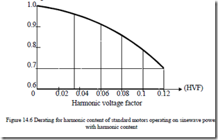
The rise of switching frequency in recent years for PWM static power converters for low and medium power IMs has led to a significant reduction of voltage time harmonic content at motor terminals. Consequently, the derating has been reduced. NEMA 30.01.2 suggests derating the induction motor as a function of harmonic voltage factor (HVF), Figure 14.6.
Reducing the HVF via power filters (active or passive) becomes a priority as the variable speed drives extension becomes more and more important. In a similar way, when IMs designed for sinewave power source are fed from IGBT PWM voltage source inverters, typical for induction motors now up to 2MW (as of today), a certain derating is required as additional winding and core losses due to voltage harmonics occur.
This derating is not yet standardized, but it should be more important when power increases as the switching frequency decreases. A value of 10% derating for such a situation is now common practice.
When using an IM fed from a sinewave power source with line voltage VL through a PWM converter, the motor terminal voltage is somewhat reduced with respect to VL due to various voltage drops in the rectifier and inverter power switches, etc.
The reduction factor is 5 to 10% depending on the PWM strategy in the converter.
VOLTAGE AND FREQUENCY VARIATION
When matching an induction motor to a load, a certain supply voltage reduction has to be allowed for which the motor is still capable to produce rated power for a small temperature rise over rated value. A value of voltage variation of ±10% of rated value at rated frequency is considered appropriate (NEMA 12.44).
Also, a ±5% frequency variation at rated voltage is considered acceptable. A combined 10% sum of absolute values, with a frequency variation of less than 5%, has to be also handled successfully. As expected in such conditions, the motor rated speed efficiency and power factor for rated power will be slightly different from rated label values.
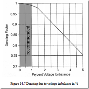
Through the negative sequence voltage imbalanced voltages may produce, additional winding stator and rotor losses. In general, a 1% imbalance in voltages would produce a 6 – 10% imbalance in phase currents.
The additional winding losses occurring this way would cause notable temperature increases unless the IM is derated (NEMA Figure 14.1) Figure
14.7. A limit of 1% in voltage imbalance is recommended for medium and large power motors.
INDUCTION MOTOR SPECIFICATIONS FOR CONSTANT V/f
Key information pertaining to motor performance, construction, and operating conditions is provided for end users’ consideration when specifying induction motors.
National (NEMA in U.S.A. [1]) and international (IEC in Europe) standards deal with such issues to provide harmonization between manufacturers and users worldwide.
Table 14.1. summarizes most important headings and the corresponding NEMA section.
Table 14.1. NEMA standards for 3 phase IMs (with cage rotors)
|
Heading |
NEMA section |
|
Nameplate markings |
NEMA MG – 1 10.40 |
|
Terminal markings |
NEMA MG – 1 2.60 |
|
NEMA size starters |
|
|
NEMA enclosure types |
|
|
Frame dimensions |
NEMA MG – 1 11 |
|
Frame assignments |
NEMA MG – 1 10 |
|
Full load current |
NEC Table 430 – 150 |
|
Voltage |
NEMA MG – 1 12.44, 14.35 |
|
Impact of voltage, frequency variation |
|
|
Code letter |
NEMA MG – 1 10.37 |
|
Starting |
NEMA MG – 1 12.44, 54 |
|
Design letter and torque |
NEMA MG – 1 12 |
|
Winding temperature |
NEMA MG – 1 12.43 |
|
Motor efficiency |
NEMA MG – 12 – 10 |
|
Vibration |
NEMA MG – 17 |
|
Testing |
NEMA MG – 112, 55, 20, 49 / IEEE-112B |
|
Harmonics |
NEMA MG – 1 30 |
|
Inverter applications |
NEMA MG – 1, 30, 31 |
Among these numerous specifications, that show the complexity of IM design, nameplate markings are of utmost importance.
The following data are given on the nameplate:
a. Designation of manufacturer’s motor type and frame
b. kW (HP) output
c. Time rating
d. Maximum ambient temperature
e. Insulation system
f. RPM at rated load
g. Frequency
h. Number of phases
i. Rated load amperes
j. Line voltage
a. Locked-rotor amperes or code letter for locked-rotor kVA per HP for motor
½ HP or more
b. Design letter (A, B, C, D, E)
c. Nominal efficiency
d. Service factor load if other than 1.0
e. Service factor amperes when service factor exceeds 1.15
f. Over-temperature protection followed by a type number, when overtemperature device is used
g. Information on dual voltage/frequency operation conditions
Rated power factor does not appear on NEMA nameplates, but is does so according to most European standards.
Efficiency is perhaps the most important specification of an electric motor as the cost of energy per year even in an 1 kW motor is notably higher than the initial motor cost. Also, a 1% increase in efficiency saves energy whose costs in 3 to 4 years cover the initial extra motor costs.
Standard and high efficiency IM classes have been defined and standardized by now worldwide. As expected, high efficiency (class E) induction motors have higher efficiency than standard motors but their size, initial cost, and locked-rotor current are higher. This latter aspect places an additional burden on the local power grid when feeding the motor upon direct starting. If softstarting or inverter operation is used, the higher starting current does not have any effect on the local power grid rating. NEMA defines specific efficiency levels for design B and E (high efficiency) IMs (Table 14.2).
On the other hand, EU established three classes EFF1, EFF2, EFF3 of efficiencies, giving the manufacturers an incentive to qualify for the higher classes.
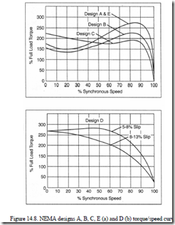
The torque/speed curves reveal, for constant V/f fed IMs, additional specifications such as starting, pull-up, and breaking torque for the five classes (letters: A, B, C, D, E design) of induction motors (Figure 14.8).
The performance characteristics of the A, B, C, D, E designs are summarized in Table 14.3 from NEMA Table 2.1 with their typical applications.
Table 14.3. Motor designs (after NEMA Table 2.1)
|
Classification |
Locked rotor torque (% rated load torque) |
Breakdown torque (% rated load torque) |
Locked rotor current (% rated load current) |
Slip % |
Typical applications |
Rel. η |
|
Design B Normal locked rotor torque and normal locked rotor current |
70 – 275* |
175 – 300* |
600 – 700 |
0.5 – 5 |
Fans, blowers, centrifugal pumps and compressors, motor – generator sets, etc., where starting torque requirements are relatively low |
Medium or high |
|
Design C High locked rotor torque and normal locked rotor current |
200 – 250* |
190 – 225* |
600 – 700 |
1 – 5 |
Conveyors, crushers, stirring machines, agitators, reciprocating pumps and compressors, etc., where starting under load is required |
Medium |
|
Design D High locked rotor torque and high slip |
275 |
275 |
600 – 700 |
High peak loads with or without fly wheels, such as punch presses, shears, elevators, extractors, winches, hoists, oil – well pumping and wire – drawing machines |
Medium |
|
|
Design E IEC 34-12 Design N locked rotor torques and currents |
75 – 190* |
160 – 200* |
800 – 1000 |
0.5 – 3 |
Fans, blowers, centrifugal pumps and compressors, motor – generator sets, etc. where starting torque requirements are relatively low |
High |
Note – Design A motor performance characteristics are similar to those for Design B except that the locked rotor starting current is higher than the values shown in the table above * Higher values are for motors having lower horsepower ratings.


