So far the rotor surface core losses, rotor and stator tooth flux pulsation core losses, and space harmonic cage losses have been included in stray load losses. They all have been calculated for motor no-load, then corrected for load conditions by adequate amplification factors.
Insulated and noninsulated, skewed and nonskewed bar rotors have been investigated. Chorded pitch and full pitch windings cause differences in terms of stray losses. Other components such as end-connection leakage flux produced losses, which occur in the windings surroundings, have been left out as their study by analytical methods is almost impractical. In high power machines, such losses are to be considered.
Based on analysis, such as the one corroborated above, with those of [12], we line up a few rules to reduce full load stray losses
• Large number of slots per pole and phase, q, if possible, to increase the first phase belt and first slot (opening) harmonics.
• Insulated or large transverse resistance cage bars in long stack skewed rotors to reduce transverse cage losses.
• Skewing is not adequate for low transverse resistance as is does not reduce the stray cage losses while the transverse cage losses are large. Check the tooth flux pulsation core losses in skewed rotors.
• Nr < Ns to reduce the differential leakage coefficient of the first slot (opening) harmonics Ns ± p1, and thus reduce the transverse cage losses.
• For Nr < Ns, skewing may be eliminated after the parasitic torques are checked and found small enough. For q = 1, 2, skewing is mandatory.
• Chorded coil windings with y/τ ≈ 5/6 are adequate as they reduce the first phase belt harmonics.
• With full pitch winding, use large numbers of slot/pitch/phase whenever possible.
• Skewing seems efficient for noninsulated rotor bars with high transverse resistance as it reduces the transverse rotor losses.
• With delta connection (Ns−Nr) ≠ 2p1, 4p1, 8p1.
• With parallel path winding, the circulating stator currents induced by the bar current mmf harmonics have to be avoided by observing a certain symmetry.
• Use small stator and rotor slot openings, if possible, to reduce the first slot opening flux density harmonics and their losses. Check the starting and peak torque as they tend to decrease due to slot leakage inductance increase.
• Use magnetic wedges for open slots, but check for the additional eddy current losses in them and secure their mechanical ruggedness.
• Increase the airgap, but maintain good power factor and efficiency.
• For one conductor per layer in slot and open slots, check that the slot opening bos,r to elementary conductor ds,r are bos/ds ≤ 1, bor/dr ≤ 3. This way, the stray load conductor losses by space harmonics fields are reduced.
• Use sharp tools and annealed lamination sheets (especially for low power motors), to reduce surface core losses.
• Return rotor surface to prevent laminations to be short-circuited and thus reduce rotor surface core losses.
• As storing the motor with cast aluminum (noninsulated) cage rotors after fabrication leads to a marked increase of rotor bar to slot wall contact electrical resistivity, a reduction of stray losses of (40 to 60)% may be obtained after 6 months of storage.
11.10. HIGH FREQUENCY TIME HARMONICS LOSSES
High frequency time harmonics in the supply voltage of IMs may occur either because the IM itself is fed from a PWM static power converter for variable speed or because, in the local power grid, some other power electronic devices produce voltage time harmonics at IM terminals.
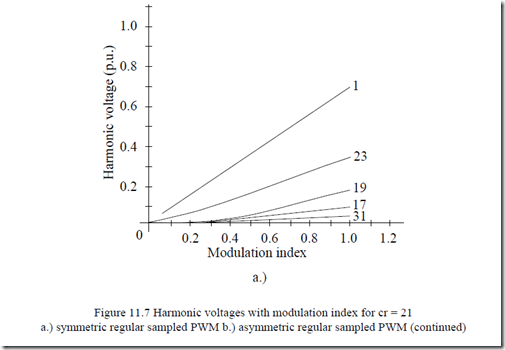
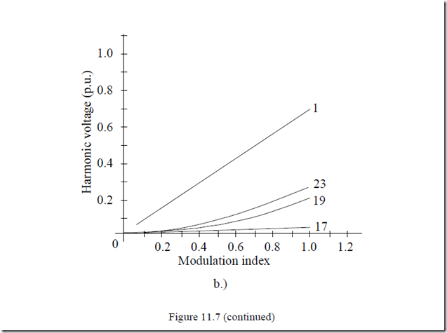
For voltage-source static power converters, the time harmonics frequency content and distribution depends on the PWM strategy and the carrier ratio cr (2cr switchings per period). For high performance symmetric regular sampled, asymmetric regular sampled, and optimal regular sampled PWM strategies, the main voltage harmonics are (cr ± 2)f1 and (2cr ± 1)f1, respectively, [13], Figure 11.7.
It seems that accounting for time harmonics losses at frequencies close to carrier frequency suffices. As of today, the carrier ratio cr varies from 20 to more than 200. Smaller values relate to larger powers.
Switching frequencies up to 20 kHz are typical for low power induction motors fed from IGBT voltage-source converters. Exploring the conductor and core losses up to such large frequencies becomes necessary.
High carrier frequencies tend to reduce the current harmonics and thus reduce the conductor losses associated with them, but the higher frequency flux harmonics may lead to larger core loss. On the other hand, the commutation losses in the PWM converter increase with carrier frequency.
The optimum carrier frequency depends on the motor and the PWM converter itself. The 20 kHz is typical for hard switched PWM converters. Higher frequencies are practical for soft switched (resonance) converters. We will explore, first rather qualitatively and then quantitatively, the high frequency time harmonics losses in the stator and rotor conductors and cores.
At high carrier frequency, the skin effect, both in the conductors and iron cores, may not be neglected.
11.10.1. Conductor losses
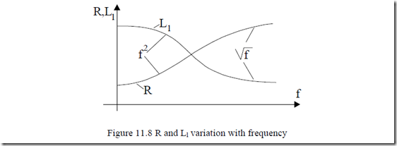
The variation of resistance R and leakage Ll inductance for conductors in slots with frequency, as studied in Chapter 9, is at first rapid, being proportional to f2. As the frequency increases further, the field penetration depth gets smaller than the conductor height and the rate of change of R and Ll decreases to become proportional to f½ (Figure 11.8).
For the end connections (or end rings), the skin effect is less pronounced, but it may be calculated with similar formulas providing virtual larger slots are defined (Chapter 9, Figure 9.10).
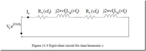
For high frequencies, the equivalent circuit of the IM may be simplified by eliminating the magnetization branch (Figure 11.9).
Notice that the slip Sν ≈ 1.
In general, the reactances prevail at high frequencies,
For a given (fixed) value of the current harmonic Iν, the conductor losses will increase steadily with frequency. This case would be typical for current control.
For voltage control, when voltage harmonics Vν are given, however, (11.96) shows that it is possible to have conductor losses increasing with frequency if the decrease of leakage inductance Lσ(fν) with fν and the increase factors of (Rs( )fν + Rr ( )fν ) with fν are less than proportional to fν2.
Measurements have shown that the leakage inductance decrease to 0.5 to 0.3 of the rated frequency (60 Hz) value at 20 kHz. So, in general,
Lσ ν( )f ≈ K fL ν−0.16 (11.97)
For high frequencies Rr variation with frequency is in the fν0.5 range, approximately, so the rotor conductor losses are
Pconr ![]() (2πf Kν L )2fν 0.32 K fR ν0.5 ~ fVν1.18h2 (11.98)
(2πf Kν L )2fν 0.32 K fR ν0.5 ~ fVν1.18h2 (11.98)
The rotor conductor losses drop notably as the time harmonic frequency increases.
The situation in the stator is different as there are many conductors in every slot (at least in small power induction machines).
So the skin effect for Rs will remain fν dependent in the initial stages (KRs = CRs⋅ fν),
Pcons ~ Vν ν2f 0.32 (11.99) The stator conductor losses tend to increase slightly with frequency. For large power IMs (MW range) the stator conductor skin effect is stronger and the situation comes closer to that of the rotor: the stator conductor losses slightly decrease at higher frequencies. We should also mention that the carrier frequency in large power is only 1 to 3 kHz.
For low and medium power motors, as the carrier frequency reaches high levels (20 kHz or more), the skin effect in the stator conductors enters the fν0.5 domain and the stator conductor losses, for given harmonic voltage, behave like the rotor cage losses (decrease slightly with frequency (11.98)). This situation occurs when the penetration depth becomes smaller than conductor height.
11.10.2. Core losses
Predicting the core loss at high frequencies is difficult because the flux penetration depth in lamination becomes comparable with (or smaller than) the lamination thickness.
The leakage flux paths may then prevail and thus the reaction of core eddy currents may set up significant reaction fields.
The field penetration depth in laminations δFe is
σFe–iron electrical conductivity; µFe–iron magnetic permeability.
For f = 60 Hz, σFe = 2⋅106 (Ωm)-1, µFe = 800 µ0, δFe = 1.63 mm, while at 20 kHz δFe = 0.062 mm. In contrast for copper (δCo)60Hz = 9.31 mm, (δCo)20kHz = 0.51 mm and in aluminum (δAl)60Hz = 13.4 mm, (δAl)20kHz = 0.73 mm.
The penetration depth at 800µ0 and 20 kHz, δFe = 0.062 mm, shows the importance of skin effect in laminations. To explore the dependence of core losses on frequency, let us distinguish three cases.
• Case 1 – No lamination skin effect: δFe >> d
This case corresponds to low frequency time harmonics. Both hysteresis and eddy current losses are to be considered.
PFe = (K ‘Bhl νnfν + K ‘Bel ν ν2f 2 )A ll (11.101) where Bν is the harmonic flux density:
Bν = Al 2πf Aν l
Al is the effective area of the leakage flux path and l is its length. With (11.102), (11.101) becomes
PFe = (K Vhl νnfν1−n + K V A lel ν) l (11.103) Since n > 1, the hysteresis losses decrease with frequency while the eddy current losses stay constant. PFe is almost constant in these conditions.
• Case 2 – Slight lamination skin effect, δFe ≈ d When δFe ≈ d, the frequency fν is already high and thus δAl < dAl and a severe skin effect in the rotor slot occurs. Consequently, the rotor leakage flux is concentrated close to the rotor surface. The “volume” where the core losses occur in the rotor decreases. In general then, the core losses tend to decrease slowly and level out at high frequencies.
• Case 3 – Strong lamination skin effect, δFe < d
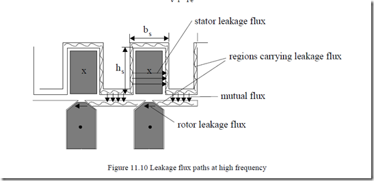
With large enough frequencies, the lamination skin depth δFe < d and thus the magnetic field is confined to a skin depth layer around the stator slot walls and on the rotor surface (Figure 11.10).
The conventional picture of rotor leakage flux paths around the rotor slot bottom is not valid in this case.
The area of leakage flux is now, for the stator, Al = lf δFe, with lf the length of the meander zone around the stator slot.
lf = (2hs + bs )Ns (11.104)
Now the flux density Bν is
Bν = f lK Vν νδFe ~ Kfν− 12 (11.105) ν f
Consequently, the core losses (with hysteresis losses neglected) are
2f 2l lf stackδFe ~ K V1 ν ν2f 12 (11.106)
PFee = K Be ν ν
A slow steady state growth of core losses at high frequencies is thus expected.
11.10.3. Total time harmonics losses
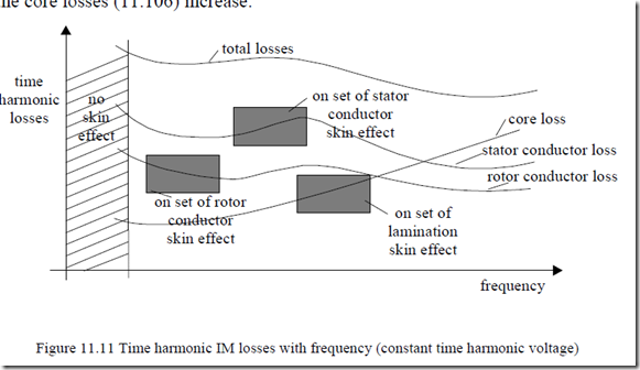
As the discussion above indicates, for a given harmonic voltage, above certain frequency, the conductor losses tend to decrease as fν-1.2 (11.98) while the core losses (11.106) increase.
Consequently, the total time harmonics may level out above a certain frequency (Figure 11.11). Even a minimum may be observed. At what frequency such a minimum occurs depends on the machine design, power, and PWM frequency spectrum.
