Contactors
Contactors are very similar to relays. They are specifically designed for switching load currents. They are used to supply electric motors, heaters, lamps etc. Contactors are designed for high switching frequency, long life and short switching times. The making / breaking capacity of the main contacts is matched to the possible motor starting current. High value overload currents or short circuit currents can damage the main contacts, therefore protection must be provided by fuses or MCB’s.
Generally contactors have three main contacts plus one auxiliary contact. The current rating of the main contacts will depend on the load to be switched and may be as low as 10 Amps or as high as 2000 Amps. The current rating of the auxiliary contact(s) is generally around 10 Amps.
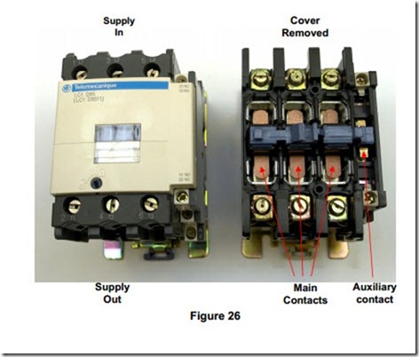
Figure 26 shows a 65 Amp contactor. The 3 Phase supply is connected to the three main terminals on the top of the contactor. The load is connected from the three main terminals on the bottom. On the right hand side of figure 26, the cover has been removed to show the three main contacts and one of the auxiliary contacts.
Note the difference in the physical size of the main ( 65 Amp ) contacts and the auxiliary ( 10 Amp ) contact.
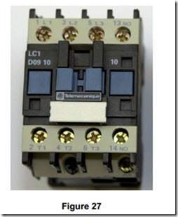
Figure 27 shows a 9 Amp contactor which is suitable for any motor up to 4 kW. On this size of contactor the auxiliary contact appears to be the same as the main contacts. The difference is only visible on dismantling the contactor and examining the contacts. The auxiliary contact is not designed to switch power to or from a load such as a motor. If used for such a purpose it would quickly fail. The coil terminals are located towards the base of the contactor. A1 is top left and A2 is available both top right and bottom right.
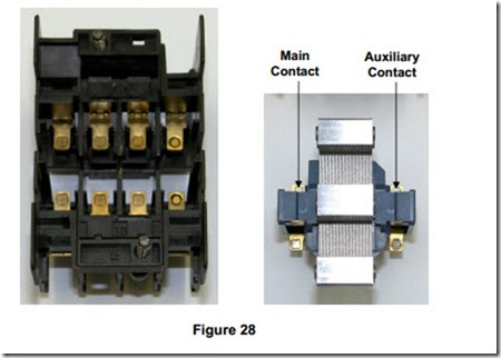
Figure 28 shows the contact arrangement inside the contactor. The difference between the three main contacts and the auxiliary contact is visible.
Auxiliary Contact
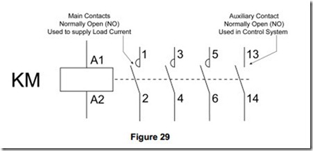
Each main contact is identified by a single digit number. The coil terminals are marked A1 and A2. The coil, of a contactor used to switch supply to a motor is usually identified by the letters KM, followed by a digit up to the total number involved in the system, e.g. KM1 to KM5.
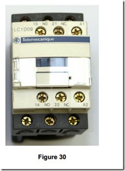
Figure 30 shows a more modern 9 Amp contactor. The most noticeable differences are;
· The inclusion of a normally closed auxiliary contact
· The position of the auxiliary contacts
· The position of the coil terminals
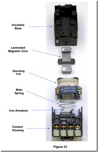
Figure 31 shows the main parts of a contactor. It consists of an insulated base which houses a laminated magnetic core. This core is mounted on rubber for quiet operation. The operating coil is fitted between the magnetic core and the armature which carries the moving contacts. When the correct supply is applied across the terminals of the coil, magnetism is produced and the armature is pulled towards the magnetic core. This movement occurs very fast and operates the contactor contacts. Each contact is spring-loaded to ensure positive closure and minimum contact bounce. When supply is disconnected from the coil, the armature is quickly returned to its original position by the main spring.
Contactor Coils
The coils of most modern contactors can be quickly changed without the use of any special tools. These contactor coils may be AC or DC operated.
AC standard coil voltages are 24, 110, 230, 400 Volts 50 Hz.
DC standard coil voltages are 12, 24, 48, 230 Volts DC. Other non-standard voltage ratings are available on request.
It is most important that the coil voltage, type and value are matched to the supply available. A 230 Volt supply will not energise a 400 Volt coil. A 400 Volt supply will operate a 230 Volt coil, however the coil will quickly overheat and burn-out.
