REVERSIBLE SPEED CONTROL
Some industrial speed control applications require that the rotation of a motor be
reversible. That is, the motor must be able to spin either clockwise or counterclockwise,
besides having adjustable speed. Reversal of the dii>ection of rotation
can be accomplished in either of two ways:
1. Reversing the direction of the field current, leaving the armature current the
same.
2. Reversing the direction of the armature current, leaving the field current the
same.
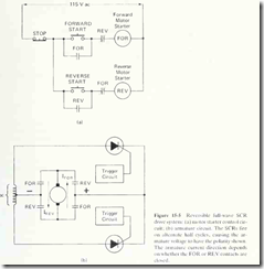
The circuits of Fig. 10-27 show how armature current direction can be reversed
in a half-wave control system. Figure 15-5 shows how armature current can be
reversed in a full-wave speed control system. The most straightforward method of
reversing armature or field current is by the use of two separate motor starter
contactors. The forward contactor causes current to go through the armature in
one direction, while the other contactor, the reverse contactor, causes current to
flow in the opposite direction.
In Fig. 15-5(a), the FOR contactor is energized by pressing the FORWARD
START pushbutton. As long as the REV contactor is dropped out at that time,
the FOR contactor will energize and seal itself in around the N.O. pushbutton
switch. The operator can then release the FORWARD START button, and the
contactor will remain energized until the STOP pushbutton is pressed.
In Fig. 15-5(b). it can be seen that when the FOR contacts are closed, the
current flows through the armature from bottom to top. thereby causing rotation
in a certain direction (assume clockwise). When the REV contacts are closed,
armature current flows from top to bottom, thus causing rotation in the counterclockwise
direction. As usual, the speed of rotation is controlled by the firing delay
of the SCRs.
Reversible full-wave control can be accomplished without the use of switchgear
(contactors, pushbuttons, etc.) with the circuit of Fig. 15-6. In Fig. 15-6, the
direction of rotation is determined by which trigger circuit is enabled. If the forward
trigger circuit is enabled, the top two SCRs will fire on alternate half cycles of the
ac line, and they will pass current through the armature from right to left. If the
reverse triggering circuit is enabled, the bottom two SCRs will fire on alternate
half cycles of the ac line, and they will pass current through the armature from left
to right, as indicated. The method of enabling one trigger circuit while disabling
the other has not been shown in Fig. 15-6.

