BASIC RECTIFIER CIRCUITS
A rectifier circuit converts ac power to dc power. The most common rectifier circuits are
1. The half-wave rectifier
2. The full-wave bridge rectifier
3. The three-phase half-wave rectifier
4. The three-phase full-wave rectifier
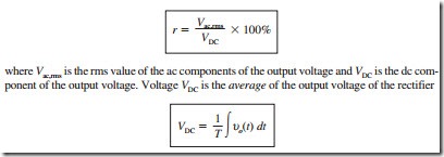
The ripple factor is a good measure of the smoothness of the dc voltage out of a recti- fier circuit. The percentage of ripple in a dc power supply is
where Vrms is the rms value of the total output voltage from the rectifier.
The Half-Wave Rectifier
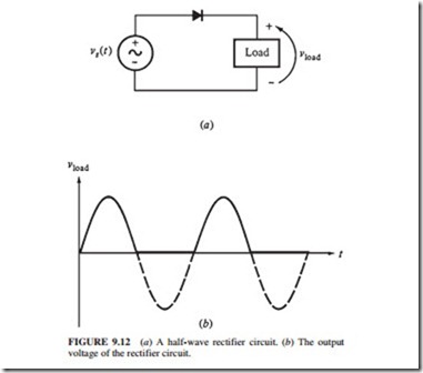
Figure 9.12 illustrates a half-wave rectifier. The current flows through the diodes on the positive half cycle, and it is blocked on the negative half-cycle. This is a poor approximation of a constant dc waveform because it contains 60-Hz ac frequency components and all the harmonics. This rectifier has a ripple factor r = 121 percent; i.e., it has more ac voltage components in its output than dc voltage components.
The Full-Wave Rectifier
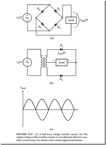
Figure 9.13a illustrates a full-wave bridge rectifier circuit. Diodes D1 and D3 conduct on the positive half-cycle, and D2 and D4 conduct on the negative half-cycle. This output voltage
is smoother than that of the previous rectifier, but it still contains ac frequency components at 120 Hz and its harmonics (r = 48.2 percent).
Figure 9.13b illustrates another possible full-wave rectifier circuit. Diode D1 conducts on the positive half-cycle with the current returning through the center tap of the trans- former, and D2 conducts on the negative half-cycle with the current returning through the center tap of the transformer. The output is shown in Fig. 9.13c.
The Three-Phase Half-Wave Rectifier
Figure 9.14 illustrates a three-phase half-wave rectifier and its output voltage. At any instant, the diode with the largest voltage applied to it will conduct, and the other two diodes will be reversed-biased. The output voltage at any time is the highest of the three input voltages. The output voltage is smoother than that of the full-wave bridge rectifier cir- cuit. It has voltage components at 180 Hz and its harmonic components (r = 18.3 percent).
The Three-Phase Full-Wave Rectifier
Figure 9.15 illustrates a three-phase full-wave rectifier. The first part of the circuit connects the highest of the three-phase voltages at any instant to the load. The second part consists of three diodes oriented with their cathodes connected to the supply voltages and anodes con- nected to the load. This arrangement connects the lowest of the three voltages to the load at any given time.
The three-phase full-wave rectifier connects the highest of the three voltages to one end of the load and the lowest voltage to the other end (Fig. 9.16). The three-phase full-wave rectifier provides smoother output than a three-phase half-wave rectifier (r = 4.2 percent).


