POWER ELECTRONICS COMPONENTS
The most important types of semiconductor devices are
1. The diode
2. The two-wire thyristor (or PNPN diode)
3. The three-wire thyristor [or silicon controlled rectifier (SCR)]
4. The gate turnoff (GTO) thyristor
5. The DIAC
6. The TRIAC
7. The power transistor (PTR)
8. The insulated gate bipolar transistor (IGBT)
The Diode
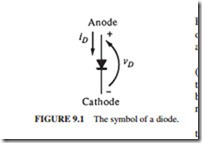
A diode is a semiconductor device that conducts current in one direction only (Fig. 9.1). The current is conducted from its anode to its cathode, but not in the opposite direction.
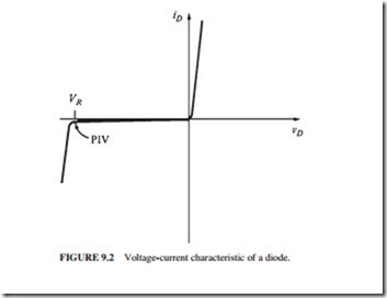
Figure 9.2 illustrates the voltage-current characteristic of a diode. A large current flows when a voltage is applied to the diode in the forward direction.
The current is limited to a very small value (microamperes or less) when a voltage is applied to the diode in the reverse direction. The diode will break and allow current in the reverse direction if the reverse voltage is large enough.
Diodes are rated by the maximum reverse voltage they can withstand before breaking down and by the
amount of power they can safely dissipate. The power dissipated by a diode during for- ward direction is equal to υDiD. This power is limited to prevent overheating the diode. The peak inverse voltage (PIV) is the maximum reverse voltage of a diode. This value must be high enough to ensure that the diode will not conduct in the reverse direction.
Diodes are also rated by their switching time. It is the time required to go from the off state to the on state, and vice versa. Power diodes are very large, high-power devices that store large charge in their junctions. They switch states much more slowly than diodes found in electronic circuits. Essentially, all power diodes can be used in 50- to 60-Hz rectifiers because they can switch states fast enough for this application. However, pulse- width modulators (PWMs) require power diodes to switch states at rates higher than 10,000 Hz. Special diodes called fast-recovery, high speed diodes are used for these very fast switching applications.
The Two-Wire Thyristor or PNPN Diode
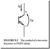
Thyristor is a name of a family of semiconductor devices which have up to four semi- conductor layers. The two-wire thyristor is a member of this family. It is also known as the PNPN diode or reverse-blocking diode-type thyristor in the IEEE standard for graphic symbols (Fig. 9.3).
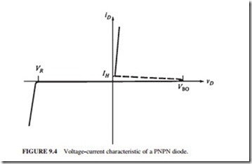
The PNPN is a rectifier or diode that has an unusual voltage-current characteristic in the forward-biased region (Fig. 9.4). Its characteristic curve consists of these regions:
1. The reverse-blocking region
2. The forward-blocking region
3. The conducting region
The PNPN diode behaves as follows:
1. It turns on when the applied voltage υD exceeds VBO.
2. It turns off when the current iD drops below IH.
3. It blocks all current flow in the reverse direction until the maximum reverse voltage is exceeded.
The Three-Wire Thyristor or SCR
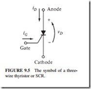
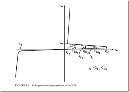
This is the most important of the thyristor family. It is also known as the silicon controlled rectifier (SCR) (Fig. 9.5). Its voltage-current characteristic with the gate lead open is the same as that of a PNPN diode. However, the breakover or turn-on voltage of an SCR can be adjusted by a current flowing into its gate lead. Voltage VBO drops when the gate current increases (Fig. 9.6). If the VBO with no gate signal is larger than the highest voltage in the circuit, then a gate current is required to turn it on. Once it is on, it remains on until its current falls
below IH. Therefore, once an SCR is triggered, its gate current can be removed without changing the state of the device.
The SCR is commonly used for switching or rectification applications. It is available in ratings ranging from a few amperes to a minimum of 3000 A. In summary, an SCR
1. Turns on when the voltage υD applied to it exceeds VBO
2. Has a breakover voltage VBO whose level is controlled by the amount of gate current iG
present in the SCR
3. Turns off when the current iD flowing through it drops below IH
4. Blocks all current flow in the reverse direction until the maximum reverse voltage is exceeded
The Gate Turnoff Thyristor
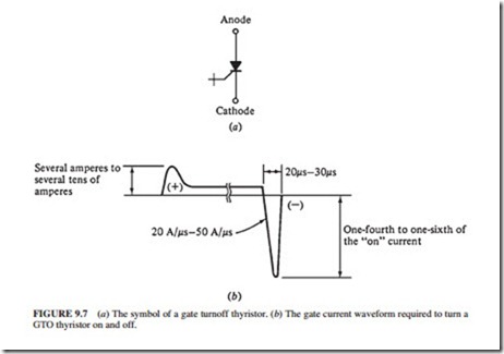
A gate turnoff (GTO) thyristor is an SCR that can be turned off by a large enough nega- tive pulse at its gate lead even if iD exceeds iH. These devices are becoming more popu- lar because they eliminate the need for external components to turn off SCRs in dc circuits (Fig. 9.7a).
Figure 9.7b illustrates a typical gate current waveform for a high-power GTO thyris- tor. The gate current required to turn on a GTO thyristor is typically larger than that of an ordinary SCR. The gate current for a large high-power device is around 10 A. A large neg- ative current pulse of 20- to 30- s duration is required to turn off the device. The magni- tude of this negative pulse must be one-fourth to one-sixth that of the current flowing through the device.
The DIAC
The DIAC behaves as two PNPN diodes connected back to back. It is turned on when the applied voltage in either direction exceeds VBO. Once it is turned on, it remains on until the current falls below IH.
The TRIAC
The TRIAC behaves as two SCRs connected back to back with a common gate lead. The breakover voltage in a TRIAC decreases with increasing gate current, as with an SCR. However, a TRIAC responds to either positive or negative pulses at its gate. Once a TRIAC is turned on, it remains on until the current falls below IH.
The Power Transistor
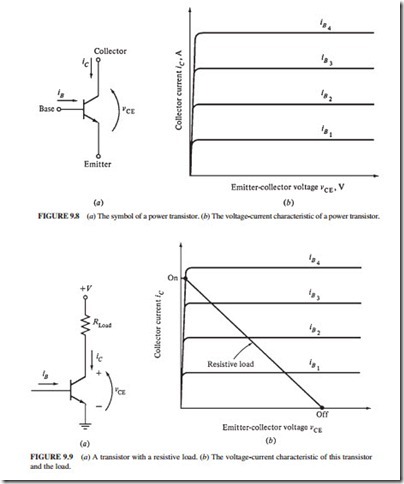
Figure 9.8a shows the symbol of a transistor. Figure 9.8b illustrates the collector-to-emitter voltage versus the collector current characteristic for a transistor. The collector current iC is directly proportional to its base current iB over a wide range of collector-to-emitter voltages (VCE).
Power transistors are normally used to switch a current on or off. Figure 9.9 shows the iC = VCE characteristic with the load line of the resistive load. Transistors are normally used as switches. They are completely on or completely off. A base current of zero will com- pletely turn off the transistor.
the transistor will not be on or off. This is highly undesirable because a large collector current will flow, dissipating a lot of power in the transistor.
If the base current is high enough, the transistor becomes completely saturated. It con- ducts without wasting a lot of power. A major drawback of large power transistors is their relatively slow switching from on to off, because a large base current is needed or removed to turn them on or off.
The Insulated Gate Bipolar Transistor (IGBT)
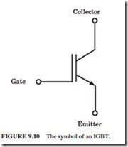
The IGBT is similar to the power transistor, except that it is controlled by the voltage applied to its gate rather than the current flowing into its base, as in power transistors. The current flowing in the gate of an IGBT is extremely small because the impedance of the control gate is very high. This device is equiv- alent to the combination of a metal-oxide semicon- ductor field effect transistor (MOSFET) and a power transistor (Fig. 9.10).
Since the current required to control an IGBT is very small, it can be switched much more quickly than a power transistor. The IGBTs are normally used in high-power, high-frequency applications.
