The VU and the Volume Indicator Instrument
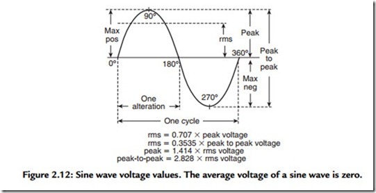
Volts, amperes, and watts can be measured by inserting an appropriate meter into the circuit. If all audio signals were sine waves, we could insert a dBm meter into the circuit and get a reading that would correlate with both electrical and acoustical variations. Unfortunately, audio signals are complex waveforms and their rms value is not 0.707 times peak but can range from as small as 0.04 times peak to as high as 0.99 times peak (Figure 2.12). To solve this problem, broadcasting and telephone engineers got together in 1939 and designed a special instrument for measuring speech and music in communication circuits. They calibrated this new type of instrument in units called
VU. The dBm and the VU are almost identical; the only difference is their usage. The instrument used to measure VU is called the volume indicator (VI) instrument. (Some users ignore this and incorrectly call it a VU meter.) Both dBm meters and volume indicator instruments are specially calibrated voltmeters. Consequently, the VU and dBm scales on these meters give correct readings only when the measurement is being made across the impedance for which they are calibrated (usually 150 or 600 Ω). Readings taken across the design impedance are referred to as true levels, whereas readings taken across other impedances are called apparent levels.
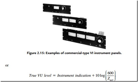
Apparent levels can be useful for relative frequency response measurements, for example. When the impedance is not 600 Ω, the correction factor of 10 log (600/new impedance) can be added to the formula containing the reference level as in the following equation:
The VU Impedance Correction
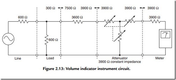
When a VI instrument is connected across 600 Ω and is indicating 0 VU on a sine wave signal, the true level is 4 dB higher, or +4 dBm, instead of 0 dBm or zero level. The reason this is so is shown in Figure 2.13. The VI instrument uses a 50-μA D’Arsonval
movement in conjunction with a copper-oxide bridge-type rectifier. The impedance of the instrument and rectifier is 3900 Ω. To minimize its effect when placed across a 600-Ω line, it is “built out” an additional 3600 Ω to a total value of 7500 Ω. The addition of this build-out resistance causes a 4-dB loss between the circuit being measured and the instrument. Therefore when a properly installed VI instrument is fed with 0 dBm across a 600 line, the meter would actually read -4 VU on its scale. (When the attenuator setting is added, the total reading is indeed 0 VU.)
Presently, no major U.S. manufacturer offers for sale a standard volume indicator that complies with the applicable standard (C16.5). The standard requires that an attenuator be supplied with the instrument and none of the manufacturers do so. What they are doing requires some attention. The instruments (usually high-impedance bridge types) are calibrated so as to act as if the attenuator were present. When the meter reads 0 VU (on a sine wave for calibration purposes), the true level is +4 dBm. This means a voltage of 1.23 V across 600 Ω will cause the instrument to read an apparent 0 VU. Note that when reading sine wave levels, the label used is “dBm.” When measuring program levels, the label used is “VU.” The VU value is always the instrument indication plus the attenuator value.
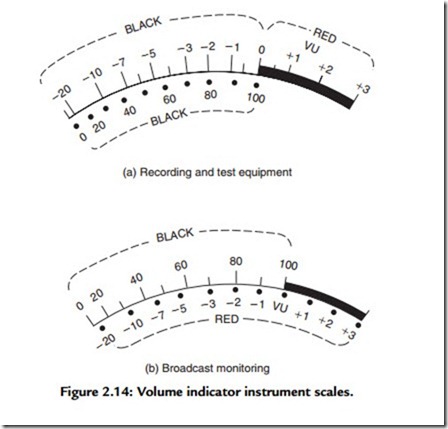
Two different types of scales are available for VI meters (Figure 2.14). Scale A is a VU scale (recording studio use), and scale B is a modulation scale (broadcast use). On complex waveforms (speech and music), the readings observed and the peak levels present are about 10 dB apart. This means that with a mixer amplifier having a sine wave output capability of
+18 dBm, you are in danger of distortion with any signal indicating more than +8 VU on the VI instrument (+18 dBm – [+10 dB] peaking factor or meter lag equals +8 VU).
Figure 2.15 shows an example of commercially available VI instrument panels used in the past that included the VI instrument and 3900-Ω attenuator, which also contains the 3600-Ω build-out resistor.
How to Read the VU Level on a VI Instrument
A VI instrument is used to measure the level of a signal in VU. In calibration:
0 VU = 0 dBm and a 1.0-VU increment is identical to a 1.0-dB increment. The true level reading in VU is found by
where, apparent level = instrument indication + attenuator or sensitivity indicator. Thus we can have the following.
1. A direct reading from the face of the instrument (zero preferred).
2. The reading from the face of the instrument plus the reading from the attenuator or other sensitivity adjustment—normally a minimum of +4 dB or higher. When the instrument indicates zero, the apparent level is the attenuator setting.
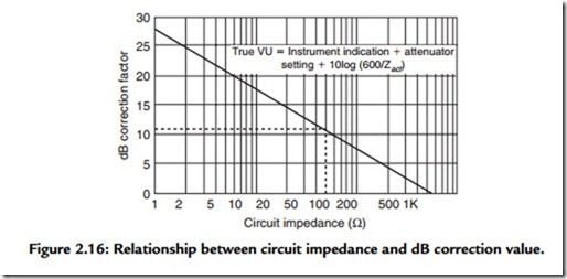
3. The correction factor for impedance other than the reference impedance. 600 Ω is the normal impedance chosen for a reference, but any value can be used so long as the voltage across it results in 0.001 W (Figure 2.16).
Example
We have an indication on the instrument of -4 VU. The sensitivity control is at +4. We are across 50 Ω (a 100-W amplifier with a 70.7-V output). Using Figure 2.16, our true VU
would be -4 VU + (+4 VU) + 10.8 correction factor = 10.8 VU.
Calibrating a VI Instrument
The instrument should be calibrated to read a true level of zero VU when an input of a 1000-Hz steady-state sine wave signal of 0 dBm (0.001 W) is connected to it. For example, typical calibration is when the instrument indicates -4, the attenuator value is +4, and it is connected across a 600 circuit. Levels read on a VI instrument when the source is the aforementioned sine wave signal should be stated as dBm levels.
Reading a VI Instrument on Program Material
Because of the ballistic properties of VI instruments, they exhibit what has been called “instrument lag.” On short-duration peak levels, they will “lag” by approximately 10 dB.
Stated another way, if we read a true VU level of +8 VU on a speech signal, then the level in dBm becomes +18 dBm. This means that the associated amplification equipment, when fed a true VU level of +8 VU, must have a steady-state sine wave capability of +18 dBm to avoid overload.
Rule
Levels stated in VU are assumed to be program material, and levels stated in dBm are assumed to be steady-state sine wave.
Reading Apparent VU Levels
Volume indicator instruments can be used to read apparent or relative levels. If, for example, you know that overload occurs at some apparent level, you can use that reading as a satisfactory guide to the system’s operation, even though you do not know the true level. When adjusting levels using the instrument to read the relative change in level, such as turning the system down 6 dB, you do not need to do so in true level readings. Instrument indication serves effectively in such cases.
When being given a level, be sure to ascertain whether it is:
1. An instrument indication.
2. An apparent level.
3. A true level.
4. A relative level.
5. A calibration level.
6. A program level.
7. None of the above but simply an arbitrary meter reading.
Special Note: Well-designed mixers have instruments that indicate the available input power level to the device connected to its output. Such levels are true levels.
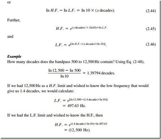
Calculating the Number of Decades in a Frequency Span
To find the relationship of the number of decades between the lowest and the highest frequencies, use the following equations:
