Generation of an Alternating EMF
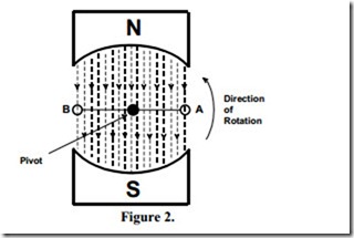
Figure 2 shows a cross-section through a single loop generator.
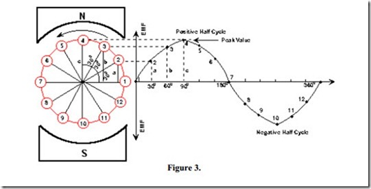
As the single loop coil AB is being rotated anticlockwise about its pivot we will consider what voltage, if any, is being induced into this coil at definite intervals throughout a 3600 cycle of rotation, starting at positions 1 and 7, see Figure 3.
When the coil sides A and B are rotating parallel to the lines of magnetic flux and hence not cutting any lines of magnetic flux no EMF is being induced in them. This is illustrated in Figure 3, by positions 1 and 7,
As the coil AB is rotated further anticlockwise, it can be seen that the coil is cutting magnetic flux lines and hence an EMF is induced into it. This is illustrated in Figure 3, by positions 2 and
8. The magnitude of this EMF is as shown at position 2 of the sine wave.
As the coil AB is rotated further anticlockwise through positions 3 and 9, and then to positions 4 and 10 where the maximum flux is being cut resulting in the maximum voltage being induced into the coil as illustrated at position 4, see Figure 3.
As the induced EMF in the coil AB depends on the amount of flux being cut, which itself depends on the position of the coil, then the magnitude of the induced EMF can be represented by the coil position.
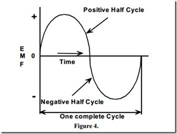
The resulting graph, Figure 4, indicates the EMF induced in the coil for one complete revolution of the coil. The resultant waveform is called a sine wave.
A sine waveform consists of equal positive and negative half cycles.
Figure 4 shows the variation of the induced EMF during one complete revolution of a coil and is termed one cycle.
Related posts:
Incoming search terms:
- generation of alternating emf
- what is alternating emf
- production of alternating EMF
- generation of emf
- generation of an alternating emf
- How alternating EMF generated explain?
- Production of an alternating e m f
- the generation of alternating Emf with diagram
- what causes the variation in EMF in generators
- what is generation of alternating emf
- what is the production of an alternating electromotive force
- generation of emf an illustration
- alternating emf
- alternating emf generated expression
- diagram the generation of an alternating E M F
- e m f alternating generation
- generation of ac emf
- Generation of alternating emf in ac
- generation of alternative emf
- Generation of alternative emf pdf
- Generation of an AC emf
- With diagram explain the generation of alternative emf


