Motor Winding
Motor coils may be wound with a single wire or several wires in hand, but in either case, the coils are wound practically the same except that more forming is required where there are several wires in hand.
Sometimes it is desirable to use two or more wires in hand instead of a single wire because the smaller wires are easier to form than the larger single wire. Also, the shop may not have the proper size larger wire in stock, whereas the smaller multiwires can be substituted. The substitu tion is made by dropping the size to one-third size below the larger wire. For example, if one AWG 16 wire is required, two 18 AWG wires may be used instead.
Some winders wind the coils with two or three wires in hand where there are two or more coils per slot. This saves time because the winder can wind more than one coil at a time. In using this method, sleeve the wire with both the beginning (bottom) lead and the ending (top) lead sleeves color-coded for the separate coils. Leave the sleeves for the begin ning leads, and slide the other sleeves along the wire until the required number of turns for the coil is reached. Leave the sleeves as the top lead sleeves.
If it is not desirable to carry the sleeves on the wire, merely color the leads as the winding progresses, using a test lamp to find the top lead and the corresponding bottom lead.
The length of the coil is sometimes determined by winding a sample coil to obtain the proper length. The wires for the sides are sleeved with the proper colored sleeves, or colored the proper colors. The coils are then wound with precut wires, saving time in sleeving and making all the coils the same length. It also eliminates the necessity of dragging the wire from the spool as the motor is being wound.
Before starting the procedure of wiring or winding ac motors, the following terms and definitions should be thoroughly understood.
Coil group: The number of coils for one phase for one pole. The equation for determining a coil group is therefore
Full-pitch coil span: The coils that span from a slot in one pole to a corresponding slot or position in the next pole. The equation for deter mining the full-pitch coil span is
In general, full pitch is lOOo/o pitch. In some cases, however, a winding may be more than full pitch but seldom, if ever, exceeds 150o/o pitch.
Electrical degrees per slot: The term commonly used to express the portion of the pole which one slot covers. The equation for determining the electrical degrees per slot is
MOTOR WINDING
Once the slots have been insulated as discussed in Chapter 20, begin the winding by placing the armature in a rack or other suitable mounting device so that the commutator faces the winder. The wire is then taken in either hand-whichever is more convenient-as it is wound from a suit able rack or in its proper length as in the case of precut coils. A piece of sleeving is placed over the wire, and the end of the wire is placed so it faces the commutator.
The winder continues by winding the wire in the slot, beginning with the wire entering between the slot papers of the slot containing the bot tom side of the coil and continuing on through that slot to the back end of the armature (the end opposite the commutator). The wire is then brought across the back of the armature to the other slot containing the other side of the coil span. It enters this slot from the back and is run through to the commutator end of the armature, where it crosses andre enters the slot which it previously passed through. This procedure is repeated until the proper number of turns per coil is obtained, after which
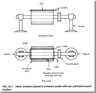
the wire is brought out to the commutator and cut off. A sleeve placed on this end of the wire completes the coil. See Fig. 22-1.
Although Fig. 22-1 shows only 2 strands of wire, in actual practice many more will be present, such as 15 strands or turns. Once one coil is wound in the manner already described, the leads are cut to length so they will reach the commutator, and then the leads are sleeved. This same procedure is repeated until the required number of coils have been wound, filling every slot.
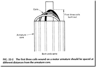
To keep the windings looking neat, the first few coils should be wound so they will build out from the armature core toward the end of the shaft as shown in Fig. 22-2 and wound as close to the shaft as possible. After the third coil has been completed, the remaining coils should be wound so they will build up from the shaft toward the circumference in stead of out toward the end of the shaft. However, never allow the wind ings to build up or out too much as this will allow them to be out of bal ance and become unsightly. Always wind the coils so as to keep the end of the winding, as well as the roundness, uniform. This can be accomplished by spreading or compacting the coils as they are wound, whichever way is necessary to keep them uniform.
Besides being uniform and neat, the winding must be firm at the ends of the slots where the coil has to travel across for the other coil side. This can be done by pressing each turn against the end of the winding with the thumb as it is wound.
When winding the coils in the slots, make certain that the slot papers do not slide, causing the winding to touch the stator laminations on one side; if so, they are likely to become shorted or grounded. Just keep an eye on the papers as the work progresses and adjust any that slip. Also try to keep all the papers in the slots so the end of the paper is the same distance from one lamination on the coil as it is from another.
One of the best ways to understand how armatures are wound is to watch an experienced winder perform the various steps. If this is not possible, examine some armatures that are already wound. Before removing old windings from an armature, carefully study how they are placed into the various slots and then make notes that can be referred to as the new windings are installed.
Before the winding is completed, slot sticks must be installed in the slots to hold the coils in place. These sticks can be put in as the armature is being wound or when the winding job is completed. In cases where the armature leads are brought back through the same slots (top and bottom leads in same slot), it is best to wait until the winding is completed before the sticks are installed. In conventional windings, however, the sticks may be installed at any time after any slot has both coil sides in it for the proper number of coils per slot. In either case, cut off the feeder paper
even with the top of the slot, being sure the wires stick up so they may be cut into when the paper is cut off. Fold each side of the paper over the winding to form an envelope, which holds the wires inside the paper.
Push or lightly tap a slot stick in over the folded papers, holding them securely down. If the slot stick goes in loosely, two may be required to adequately hold the coils in place. If two cannot be placed in the slot, take part of the paper that was previously cut off and place it in the slot full length; this will tighten the stick. The stick itself should be the same length as the paper.
Anything that will hold the coil in the slot is permissible, but manu factured slot sticks just for the purpose are better as they are easier to use and will usually offer a better, more uniform fit.
FORM-WOUND ARMATURES
Since hand-wound armatures are not gauged, so to speak, coils will nat urally not be of the same size when the job is completed. For this reason, the hand-wound armatures may be slightly out of balance, and often weights must be added to balance them. Form-wound armatures, on the other hand, are rarely out of balance due to the method by which they are wound and installed.
In form winding, the diamond coil is probably the most frequently used, but other shapes can be used if necessary. The type of coil selected and the way it is wound will depend largely on the type of old coil re moved from the motor, so be sure to save one of the existing coils as a guide during the stripping of the old winding. In case the coil in the arma ture is of the pulled type with a twisted knuckle, save at least two samples of the old winding, one showing the coil when twisted and the other straightened out to act as a template for making a coil form.
The leads in a form-wound coil may come out any number of places. Regardless of how the coil may be wound and taped or how the leads come out and other factors, the new coil should be an exact duplicate of the old ones.
The equipment for making diamond-shaped coils with twisted ends include a loop coil winder, some tin or lead cleats, pattern pliers, and two hardwood blocks with grooves about 3/4 % in. deep and the width of the coil. The length of these blocks should be approximately 1/2 – 3/4 in. longer than the length of slots through the armature.
Where there is more than one coil per slot, the amount of wire in hand is the same as the number of coils per slot. These coils are wound on the loop winder tightly and uniformly (see Fig. 22-3) in layers, leaving leads long enough for a regular connection. The tightness and the fact that they are laid in layers makes the shape proper for twisting. Instead of tying, however, the coils are fastened together by means of tin cleats, taking care not to punch or change the form of the layers of the coil in any way. Four cleats are the usual number needed on a small coil. Once the coil is securely fastened, it may be removed from the loop winder.
First, one wooden block is fastened into a bench vise, and the coil is slipped into the groove, with a cover block placed over it. By pulling the second block with both hands, coils are spread to their proper distance. The angles for the coil sides are made by pulling the coil above or below the centerline of the coil while held in the vise. The twist in the ends is made by holding the pliers on the ends of the coils and twisting in the direction of the desired twist, making sure to keep the same twist for both ends.
The twist in the knuckle is usually begun when the coil has been pulled out about halfway. The pliers must be of the flat type so as not to damage the insulation on the wire. The first part of the twist is a half twist, after which the coil is slowly pulled out and the twist is maintained by the pliers. The coil should then be sleeved and taped exactly like the sample coil taken from the motor during stripping.
To secure the coils, bands are normally used. Obtain a pulley, a weight, tin cleats, and bronze or steel wire. The armature stand must be high enough to allow the weight to swing between them. Some means of turning the armature around is also necessary.
Fasten the wire to the armature coil by tape or string and then turn the wire on the armature circumference. The recesses for bands are insulated by a strip of fiber the width of the recess, and then the wire is wound closely together across the area containing the fiber strips. At the same time, place tin cleats under the wire at these points. Wind the wire on loosely so that the wires are close together where they are around the fiber strips and farther apart where they are taken from one strip to the other. Continue this operation until all fiber strips are covered and then, after leaving a little slack, cut the wire off and put the pulley on it and secure. Apply the weight to the pulley, allowing it to hang freely. Next, turn the armature in the direction opposite to that in which it was first turned, at the same time guiding the pulley and wire on the armature so the job will be neat.
When banding an armature, make certain that it lies below the sur face of the armature core so the bands will not rub on the stator. Also clean off . any excess soldering paste from the band with alcohol so the electrical current will not cause it to corrode.
WINDING STATORS
The diamond coil is also used to wind motor stators and is wound on a loop form as discussed previously. The size and number of wires will de pend on the type and size of motor being wound and also on the existing coils in the motor. Therefore, during stripping, one or two sample coils should be saved to use as a guide in winding the new coils.
To better understand the procedures for winding a motor stator, an actual example should be presented.
Let’s assume that a stator for a three-phase motor has 36 slots and 6 poles. Applying the formula given earlier in this chapter,
The full-pitch coil span can then be found by applying the equation
full-pitch coil span = 36/6 + 1 = 7
From the preceding, it can be seen that the first coil will span or lie in slots 1and 7 of the total 36 available.
Once the slots have been insulated as discussed in Chapter 20, begin the winding by placing one side of the first coil in any slot with the leads of the coil toward the winder. One side of the next coil is then placed in the slot to the left of the first, which will make the winding progress in a clockwise direction around the stator. Four more coils are then placed in the slots in a similar manner, leaving the top sides of all of them out.
When the bottom side of the seventh coil is placed in the seventh slot, its top side is laid on top of the first coil, and the bottom of the eighth coil is placed in the eighth slot with its top placed on top of the bottom side of the second coil. See Fig. 22-4. This may be somewhat con fusing at first, but if a stator and sample coils are used to demonstrate this procedure, as progress is made, it will quickly become easy to under stand.
While the coils of the winding just described were laid in to the left of the first, or clockwise around the stator, they can be laid either clock wise or counterclockwise, according to the shape of the end twist of the coils.
In winding stators of small size, it is usual practice to connect the coils into groups as they are fed in the slots. Note in Fig. 22-4 that the bottom lead of the first coil is connected to the top lead of the second. The top lead of the first coil and the bottom lead of the second coil are identi fied or marked with sleeving of the same color. All the remaining groups are connected together the same as the first, but the unconnected leads of the second group are marked with sleeving color different from the first and the third group with still another color. For the fourth group, how ever, the color for the first group is again used, as are the colors for the other two groups.
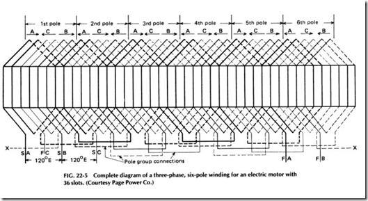
After the wedges are in the slots, the pole-group connections are made as shown in Fig. 22-5. In looking at this diagram, note that the leads for theA, B, and Cphases will show three separate windings spaced two thirds of a pole, or 120 electrical deg, apart.
A top lead of any convenient coil in the winding is selected for the start of the A phase, and all groups of a corresponding color are con nected into one winding. Then the second start or B phase is selected.
This lead must be taken from the top of the third group, counting the A phase as number 1. All groups for the B phase are then connected, and finally those for the C phase are connected. The C phase should start at the top lead of the fifth coil group, which would be the same distance from B as B is from A.
There will be six leads left,’ three starts and three finish leads, all from the top sides of the coils.


