SPIRAL-TYPE, LAP, AND WAVE WINDINGS
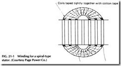
Three of the commonly used types of windings for ac motors are the spiral-type, lap, and wave windings. The spiral type has been used rather extensively on small single-phase motors and gets its name from the poles being wound in a spiral form as shown in Fig. 21-1.
In winding a spiral-type stator, the wire is started in the two slots to
be used as the center of a pole, and after winding the desired number of turns in this coil, the process is continued on in the same direction in the next pair of slots with the same wire. In this manner, the coil for one pole is built up, working from the center to the outside. Sometimes more than one slot is left empty in the center as the first winding is inserted.
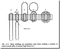
Another method used in the past is known as skein winding, shown in Fig. 21-2. In this method, the long skein coil is first made up of the right number of turns and the proper length to form the several coils. The end of this skein is then laid in the center slots as shown at A in Fig. 21-2, and the long end given one-half twist near the ends of the slots, as shown at B. The remaining end is then laid back through the next two slots- at C-and again twisted one-half turn so its sides cross near the first coil end. Then the last loop is laid back through the outer two slots to com plete the coils for this pole.
The skein method of winding is quite a time saver where a number of stators of the same size and type are to be wound. After carefully measur ing to get the first skein coil the right length, the balance of the coils can be made on the same form and the stator poles wound very rapidly.
Both lap and wave windings are also used for ac motors and alterna tors, but some of the rules given in Chapter 7 for de motor windings do not apply here. For example, instead of classifying them as parallel and series windings, as done for de windings, they are defined for ac motors as follows:
A lap winding is one in which all coils in a pole group can be traced through before leaving that group.
• A wave winding is one in which only one coil in each pole group can be traced through before leaving the group.
When used in de motors, the wave connection gives the highest volt age. This is not true of ac motors, as the wave connection gives no higher voltage than the lap. A single-circuit ac lap winding puts all possible coils in series, so it gives just as high a voltage as the wave winding. The wave winding, however, is considered stronger mechanically than the lap wind ing and for this reason is generally used for phase-wound rotors, as there is often considerable stress on their windings due to centrifugal force and starting torque.
Stators are usually wound with lap windings. However, in ac stators, the number of slots is determined by their size and the number of poles and is selected for convenience in connecting the type of winding desired for the purpose of the machine.
COIL POLARITY
When there is more than one coil per group in a motor winding, care must be given to the coil’s connections, as all coils of the same group must be connected for the same polarity- in other words, so the current flows in the same direction through all coils of the group.
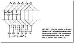
Figure 21-3 shows a simple two-pole, three-phase winding with one coil per phase group and three groups per pole. This winding only has one coil per group. Note that the groups are connected to give alternate polar ity, that is, north, south, north, etc. Also note that two coil sides per slot are present, one lying on top of the other.
The leads from the coil ends are referred to as top and bottom leads, and as the names imply, the lead from a coil side lying in the top of the slot is called the top lead, and the one from the bottom coil side is called the bottom lead.
In making the connections from one pole group to the next of the same phase, always connect like leads together, that is, bottom leads together and top leads together for the short jumper arrangement. This method should be followed to the letter to produce the alternate poles which are necessary in the winding to make the machine operate. If any of these coils are connected incorrectly, the coils will overheat, as their self-induction will be neutralized and too much current will flow.
TYPES OF COILS
Stators of 15 hp and under, and for less than 600 V, usually have partly closed slots and are commonly wound directly into the motor by the fed in method. Two types of coils are normally employed in this method: the threaded-in diamond and the basket coil, also known by other names in different shops.
Figure 21-4 shows these two types of coils which are commonly used in winding small stators with partly closed slots, as these coils can be easily fed into the narrow slot openings.
The diamond coil is wound and shaped and the ends taped with half lapped cotton tape before the coil is fed in the slots. The basket coil is simply wound to the approximate shape, and to the proper length and size, but is left untaped except for little strips of tape at the corners to hold the wires together until they are placed in the slots. The ends of these coils are taped after they are placed in the slots, or in some cases on small stators, the coil ends are left untaped. After placing the coils in the slots, their ends are shaped with a fiber drift and a rubber or rawhide mallet so the coil ends can pass over each other.
The basket coils described in this section are better suited for the smallest motors, while the fed-in coils are more suited to the larger ma chines under, say, 15 hp. The untaped sides of either of these types of coils make it possible to feed the wires one or two at a time into the nar row slot openings.
WINDING FAULTS
The greatest number of defects occurring in motor windings during ser vice or operation are caused by short circuits, open circuits, and ground faults. Water sometimes finds its way into the coils, or oil from the bear ings may have destroyed the quality of the insulation. Metallic dust and grit sometimes work into the windings and cause short circuits, or a static charge from lightning or other sources may cause punctures or small pin holes in the insulation, which result in flashovers and ground faults.
Any one of the faults mentioned in the previous paragraph is also likely to show up just after a motor has been repaired or overhauled. Therefore, all machines should be carefully checked before putting them back into service. If a motor does not operate properly after being over hauled, it is quite likely that some of the coils are connected incorrectly or that there is a short, open, or ground in some coils because of careless work during the repair.
When running, most small induction motors are almost noiseless, and even in the larger machines, only a uniform, gentle humming should be heard. This humming noise is due mostly to vibrations of core lamina tions, which are caused to vibrate slightly by the reversals of the mag netic field. In addition to this humming, which is unavoidable even in motors in perfect condition, there might also be a slight whistling sound caused by the fan blades on the rotor, friction of the air with the revolv ing parts, and air passing through ventilation ducts. This air whistling is harmless and will continue for a short period after the motor is deener gized and still turning. If a motor is unusually noisy, there is probably some defect responsible for the noise.
A deep, heavy growling is usually caused by some electrical trouble, resulting in an unbalanced condition of the magnetic field in the windings.
If a shock is felt upon touching the motor frame, it is almost certain that one or more of the coils in the winding are grounded to the core or frame. This fault can be extremely dangerous, and for this reason it is very important that all motor frames be grounded when the machine is installed. If a properly grounded coil does become shorted or grounded with the frame, the overcurrent protection normally activates at once, protecting both the motor and persons who may be in contact with the frame of the motor.


