INTRODUCTION
Induction motors are used to drive loads in various industries for powers from less than 100W to 10MW and more per unit. Speeds encountered go up to tens of thousands of rpm.
There are two distinct ways to supply an induction motor to drive a load.
• Constant voltage and frequency (constant V/f) – power grid connection
• Variable voltage and frequency – PWM static converter connection The load is represented by its shaft torque–speed curve (envelope).
There are a few basic types of loads. Some require only constant speed (constant V/f supply) and others request variable speed (variable V/f supply). In principle, the design specifications of the induction motor for constant and variable speed, respectively, are different from each other. Also, an existing motor, that was designed for constant V/f supply may, at some point in time, be supplied from variable V/f supply for variable speed.
It is thus necessary to lay out the specifications for constant and variable V/f supply and check if the existing motor is the right choice for variable speed. Selecting an induction motor for the two cases requires special care.
Design principles are common to both constant and variable speed. However, for the latter case, because the specifications are different, with machine design constraints, or geometrical aspects (rotor slot geometry, for example) lead to different final configurations. That is, induction motors designed for PWM static converter supplies are different.
It seems that in the near future more and more IMs will be designed and fabricated for variable speed applications.
TYPICAL LOAD SHAFT TORQUE/SPEED ENVELOPES
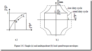
Load shaft torque/speed envelopes may be placed in the first quadrant or in 2, 3, or 4 quadrants (Figure 14.1a, b).
Constant V/f fed induction motors may be used only for single quadrant load torque/speed curves.
In modern applications (high performance machine tools, robots, elevators), multiquadrant operation is required. In such cases only variable V/f (PWM static converter) fed IMs are adequate.
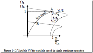
Even in single quadrant applications, variable speed may be required (from point A to point B in Figure 14.1a) to reduce energy consumption for lower speeds, by supplying the IM through a PWM static converter at variable V/f (Figure 14.2).
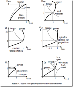
The load torque/speed curves may be classified into 3 main categories • Squared torque: (centrifugal pumps, fans, mixers, etc.)
Ω 2
TL = TLn Ωnr (14.1)
• Constant torque: (conveyors, rollertables, elevators, extruders, cement kilns, etc.)
|
• Constant power |
TL = TLn = constant |
(14.2) |
|
T = T for Lb Ω ≤ Ωr b Ω T = T b for Ω > Ω |
(14.3) |
Lb Ωr r b
A generic view of the torque/speed envelopes for the three basic loads is shown in Figure 14.3.
The load torque/speed curves of Figure 14.3 show a marked diversity and, especially, the power/speed curves indicate that the induction motor capability to meet them depends on the motor torque/speed envelope and on the temperature rise for the rated load duty-cycle.
There are two main limitations concerning the torque/speed envelope deliverable by the induction motor. The first one is the mechanical characteristic of the induction machine itself and the second is the temperature rise.
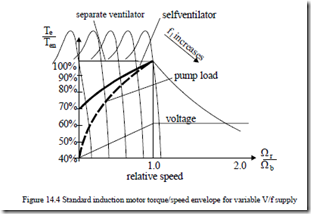
For a general purpose design induction motor, when used with variable V/f supply, the torque/speed envelope for continuous duty cycle is shown in Figure 14.4 for self ventilation (ventilator on shaft) and separate ventilator (constant speed ventilator) ,respectively.
Sustained operation at large torque levels and low speed is admitted only with separate (constant speed) ventilator cooling. The decrease of torque with speed reduction is caused by temperature constraints.
As seen from Figure 14.4, the quadratic torque load (pumps, ventilators torque/speed curve) falls below the motor torque/speed envelope under rated speed (torque). For such applications only self ventilated IM design are required.
Not so for servodrives (machine tools, etc) where sustained operation at low speed and rated torque is necessary.
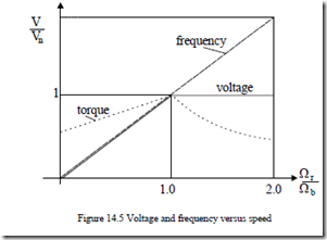
A standard motor capable of producing the extended speed/torque of Figure 14.4 has to be fed through a variable V/f source (a PWM static converter) whose voltage and frequency has to vary with speed as in Figure 14.5.
The voltage ceiling of the inverter is reached at base speed Ωb. Above Ωb, constant voltage is applied for increasing frequency. How to manage the IM flux linkage (rotor flux) to yield the maximum speed/torque envelope is a key point in designing an IM for variable speed.
