Motor Repair Techniques
Before a repair can be made to an electric motor, the fault or faults must first be determined and then a logical plan devised to accomplish the re quired work. Although the exact procedure for repairing motors will vary from motor to motor (and from fault to fault), the following is a very gen eral outline of what a motor repair job entails:
• Make all necessary tests and disassemble motor.
• Strip the armature and collect data, making a data card during the process.
• Clean and test the commutator, installng a new one if required.
• Remove old insulation from the armature.
• Wind the coils on the armature core.
• Connect and solder leads.
• Dip and bake the armature.
• Turn down the commutator and balance the armature.
• Assemble and test.
You might say that this description is a complete overhaul of a motor. Some repairs, however, will require only the replacement of, say, a commutator, a set of brushes, or the like, and obviously the entire process (as outlined) will not be necessary.
Unless an armature winding is definitely known to be defective (beyond repair) or burned out, it is advisable to test it before tearing it out. Sometimes while testing, defects may show up, but a closer examination will show that the problem is due to some foreign material that has found its way into the machine-such as a piece of copper between the bars of the commutator. By cleaning this material from within the motor, a second test may show everything to be in working order.
There are numerous tests for motor armatures, most of which have been covered in previous chapters.
COMMUTATORS
Commutators on many motors will be found to be in very bad condition and must be replaced, but before removing the old cummutator, measure ments must be taken to ensure that the new commutator will be in the correct position for the motor to operate properly. The main measure ment is the distance from the end of the shaft to the front edge of the commutator as shown in Fig. 20-1.
If the commutator is of the vertical type, allowance should be made for wear in the old commutator.
To remove the commutator from the armature shaft without damaging the shaft or stator laminations, first examine the commutator for fas teners such as pins, screws, or other devices which are holding it to the shaft. Remove any found.
Lay two bars in back of the commutator, and with an arbor press, apply pressure to the shaft and push the shaft through the commutator.
Always put a soft piece of metal on the end of the shaft so it will not be damaged. If no press is available, a hammer may be used to pound the commutator off, but be extremely careful not to chip the shaft by push ing too hard on one side. The armature should be turned as the pounding is done. Of course, if you use the pounding method, the commutator will be damaged beyond repair and cannot be used again; a new one will have to be installed. In some cases, pulley pullers can be used to good advan tage in removing old commutators from armatures shafts.
To install a new commutator, reverse the process. Of course, more care must be used in this installation because it must not be damaged at all. The best method is to press the new commutator on with an arbor or hydraulic press, but many have been installed with a length of pipe. The inside of the pipe should be just large enough to allow the shaft to enter but not so large as to rest on the bars of the commutator.
Another method is to start driving the commutator on lightly with a hammer and then turn the armature over on a place which has a hole in it for the shaft to go through. Press on the other end of the shaft if it will stand pressing and not spring. If it looks as if it would spring, then press against the armature laminations. If no press is available, a wood block held against the commutator which in turn is lightly tapped with a ham mer will work most of the time. Regardless of the method used, be ex tremely careful with this phase of the repair.
Once the armature has been stripped as described in Chapter 18 and the existing commutator is to be used, clean out the mica between the commutator bars by scratching it lightly with a knife blade file or a hack saw blade. Then use a tester between the commutator bars. If a reading is obtained, clean the slots more as there are probably metal filings present or carbon deposits or excess oil.
An extremely dirty commutator should be degreased with AWA 1,1,1 and then blown dry with compressed air before any tests are made. Of course, the wires should also be removed before making the tests.
The slots for the new windings may be cleaned out with a hacksaw or small file, or a special cutter is available from motor repair supply houses with a sharp point designed to chisel out old wires and solder. When the slots are clean, a medium-sized flat mill file is used to file over the top of the slots to remove older solder there, making it easier for the new solder to “take” when the new leads are connected to the bars.
REMOVING INSULATION
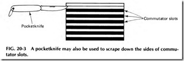
Old insulation must be removed to make room for the new and also to get rid of any that is damaged so as not to short out the new windings. The removal is easily done with a hacksaw blade beveled at its width. It is used in the slot much like a shovel is used to straighten a hole in the earth. The diagrams in Fig. 20-2 show how this is accomplished. A pocketknife may also be used to scrape down sides as shown in Fig. 20-3.
In removing the insulation, note if the insulation around the shaft and at the end of the core is in good shape. If so, do not disturb it; just coat it with schellac to preserve it better. If it is burned or otherwise
defective, it will naturally have to be removed along with the other insu lation.
After all slots have been cleaned, line up laminations properly so they will not cut the new winding when it is installed. File down any round spots on the laminated parts around the slots. Abrasive paper may do the job if the area is not too rough. Laminations are the small sheets of steel that make up the stator.
COIL AND SLOT INSULATION
In addition to the insulation on the wires themselves, it is also necessary to insulate the coils and entire winding from the slots and armature core. The insulation used for this purpose serves both to protect the coils from mechanical injury from contact with slot edges and also to electrically in sulate them from the slots. The materials commonly used for mechanical protection include fiberglass, fish paper, manila paper, fiberboard, etc.
For heat-resisting and electrical insulation, mica, micanite, mica paper, and mica cloth have been used quite extensively. Mica is a mineral which is mined in flake or sheet form and is one of the very few materials which will maintain a high dielectric strength at high temperatures. How ever, it is not very strong mechanically in its original form, but it is gen erally made up in sheets by cementing numerous thin flakes together. This is commonly called micanite and is used for insulating armature slots, between high-voltage coils, and for commutator insulation. Flexi ble sheets are made by cementing mica splittings or flakes to paper or cloth.
When reinsulating the armature exclusive of the slots, there must be enough thickness in the insulation around the shaft and on the face of the laminations to prevent a ground.
After insulating discs have been cut and placed in back of the com mutator, several thicknesses of friction tape should be used around the shaft and also where the laminations show to compensate for the de stroyed end fibers. This tape also helps hold the insulating discs in place and insulates the winding from the shaft. Once in place, it should be coated with shellac to secure it as well as to add to the insulating qualities.
Before any actual winding takes place, slot papers must be cut to size- the ones that protect the coil from becoming grounded to the lami nated core. These papers must be thick enough to withstand tearing caused by vibration, and they must not be so thick that the coil will not enter into the slot. Many winders like to save a sample of the old slot in sulation to use as a guide when matching the new insulation.
Most armatures use one thickness of insulation paper of the fiber type and one piece of oiled linen or varnished cambric. On 120-V arma tures, the winding can function satisfactorily with one .007-in. paper and one .007-in. piece of linen. If there is sufficient room, one .010-in. paper and one .007-in. piece of linen may be used. For 240 V, at least one .010-in. paper and one .010-in. piece of linen must be used. Some armatures re quire the use of .015-in. insulation papers, while others use two papers and one piece of linen.
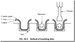
When two papers and one piece of linen are used, one of the papers is cut the same size as the linen cloth. One paper is always used as a feeder paper, since it sticks above the slot so the wire may be fed into the slot without injuring it on the laminations.
The linen and regular papers are cut so the width is such that the paper is approximately flush with the top of the slot, but an Ys in. or so of protrusion won’t hurt anything; in fact, most protrude about this distance.
The feeder paper is the same length as those of the linen and regular papers, but its width is somewhat different, since it serves as a feeder paper also. The width of the feeder is cut so that it protrudes about Y2 in.
above the slot.
The insulation paper is very important to the life of a motor, and a good grade of paper should always be used. Standard slot insulating paper is tough, absorbs varnish well, and is practically moisture f(ee. It also has strong dielectric qualities not present in wrapping paper and cardboard.
Some motor repair shops stick to the practice of insulating between coils, using a separator which is nothing more than a piece of regular fiber-type insulation paper cut slightly wider than the slot and about Ys in. longer. This paper is then bent in the middle to form a V the length of the slot. As soon as the coil is in the bottom part of the slot, the inverted V is placed in the slot and tamped down, forming a seal between the top coil half and the bottom coil half. The diagram in Fig. 20-4 illustrates how these coil separators are installed.
Another place to insulate between coils is where they intersect on the ends outside the laminated core part. This is done by laying a piece of oiled linen or cotton tape across the side of the coil just wound, so that
when the next coil is wound, it may lay on the top of tape instead of the coil below it. Nearly all plain enamel wire-wound armatures, as well as many others, use this method between coils.
Insulating between coils is compulsory on some jobs, while the prac tice is optional on others. Inspect the armature carefully to see what pro cedures are required before it is stripped. After doing so, if none of the preceding insulating techniques are necessary, it will be at the winder’s discretion whether they should be used or not.
Some armatures require that the leads be sleeved; others do not, and still some others leave sleeving up to the winder. There are many ways of sleeving the leads, such as just sleeving the bottoms and not the tops and using different colors of sleeves for each of the coils where there is more than one coil per s_lot.
Put the sleeve on the bottom, or beginning lead, and wind the coil.
When the coil is completed, put the sleeve on the ending, or top lead. Each coil is handled the same way, making the sleeves long enough to ex tend back into the slot, so they cannot be pulled off easily. It is alright if the sleeves are long enough to extend beyond the commutator; they may be cut back even with the back of the commutator.
Where there is only one sleeve used, it is usually put on the begin ning or bottom lead as the leads lay next to each other and may be shorted easily. The bottom leads lie on the top of this cloth separator. Since the top leads are easily seen, they may be kept separated from each other and therefore need no sleeving on them. Bring them out as straight as possible from the slot to the bar, making sure they are separated from each other.
Where more than one coil per slot is present, each sleeve should be given a different color, and the sequence of this color coding should be kept the same for all slots, so leads may be laid easily with no confusion. For example, the leads of the first coil could be left uncolored, while the leads of the second coil could be colored, say, red; the third, blue; and so on. These leads can be colored as they are installed on the wire during winding.
Different types of armatures will present different problems. For ex ample, some are wound by laying the bottom lead back and then bringing it through the same slot as the top lead is brought out. This is accom plished by starting the winding from the back of the armature or the side opposite the commutator, beginning with the top slot instead of the bot tom. The lead is left long enough to be brought back through the slot in the commutator. Such leads should be sleeved in such a way as to go from the back of the armature directly to the commutator. In winding this type of armature, be certain to arrange the top and bottom leads so they may easily be found. String markers and color coding are the two most often used ways of identifying them.
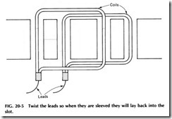
Some armatures are wound by starting out with a bottom (beginning) lead. Instead of cutting off the wire when the top lead is reached, the winder carries it back to the next slot where the next coil will begin. The wire is held in place with a finger while it is drawn out to reach the commutator, where it is then twisted around to hold it in place. This will result in the top lead of the first coil and the bottom lead of the next coil being one lead. Sleeve the leads as they are pulled and twist them so when they are sleeved they will lay back in the slot somewhat as shown in Fig. 20-5. This will help to hold the sleeving from the lead in the slot until the next coil can be wound over it.


