The two major problems for the oil-filled capacitor are open and shorted.
If the oil-filled capacitor becomes open, the full magnetizing amperes of the run winding are carried by the motor’s circuit (the circuit’s voltage drop will increase). The loss of the oil-filled capacitor won’t affect the motor’s performance, but it will make more magnetic noise.
If the oil-filled capacitor becomes shorted, the start switch and the electrolytic capacitor(s) are bypassed. The start winding is now connected directly across the line. If the motor is restarted, it draws high current and has very little starting torque. The start winding will be destroyed in a few seconds. Disconnect the shorted oil-filled capacitor, and the motor will operate satisfactorily without it.
Electrolytic Capacitor Connection Rules and Formulas
Capacitors are connected parallel, series, and in combinations of both. The reason for these connections was discussed in Chapter 3 under “Parallel Electrolytic Capacitor Connection” and “Series Electrolytic Capacitor
Connection. ”
Electrolytic capacitor connection rules are as follows:
• Capacitors connected in parallel don’t need the same microfarads (mfd) rating.
• Capacitors connected in series must have the same mfd rating.
• There are never more than two capacitors connected in series with each other. ‘TWO capacitors in series are normally a high-voltage connection.
The following electrolytic capacitor formulas determine total capacitance value for series and parallel connections and combinations of them:
• Parallel mfd ratings of each capacitor added together = total mfd
• Series mfd rating of one capacitor divided by the number of capacitors in series = total mfd
• Capacitors of unequal mfd rating in series product/ sum (example below):
cap #1 mfd x cap #2 mfd + cap # I mfd + cap # 2 mfd = total mfd
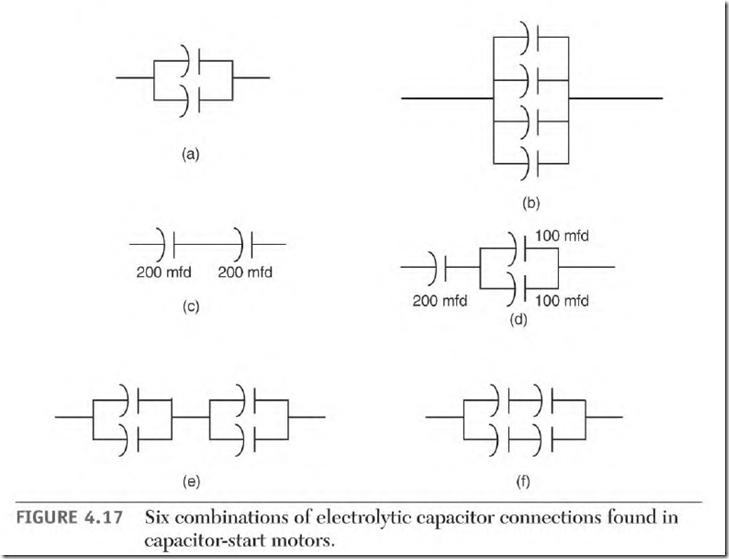
In Fig. 4.17 (a) and (b) mfd values are added together for total mfd. In part (c) the mfd value is found by dividing the mfd value of 1 by the total number of them (2).
Connection (d) adds the parallel connected capacitor’s mfd values and then divides the result by 2.
Connection (e) shows two capacitors in parallel that are in series with two capacitors in parallel. First find each parallel circuit’s value and then divide the result by 2 (the number of circuits). (Each parallel circuit must have the same mfd value.)
Connection (f) shows two capacitors in series and in parallel with two capacitors in series. (Capacitors in series must have the same mfd rating.) Divide the value of one capacitor by 2 (the number of them in series) to find the mfd of each circuit. Add the value of each circuit to get the total mfd.
Troubleshooting Electrolytic Capacitors
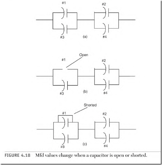
Figure 4.18 shows how mfd values change when there is a shorted or open capacitor in the connection. The multiplier Il is explained in Chapter 3 under “Capacitor Test Formula.” The number 11 applies because this is a
240-volt application. The capacitors are all rated 200 mfd and 120 volts. Using the logic of the test formula, the amperes available to the start winding can be calculated. The results explain why a motor reacts as it does when there are shorted or open capacitors.
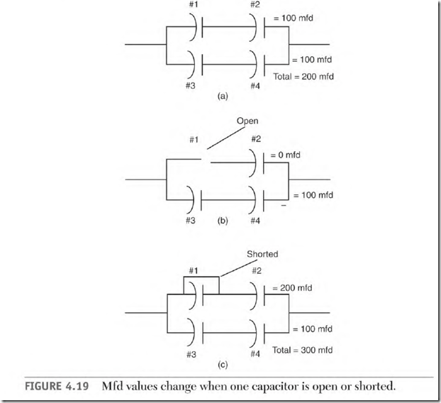
The first problem (Fig. 4.18) has two capacitors in parallel and in series with two capacitors in parallel. The second problem (Fig. 4.19) has two capacitors in series, connected in parallel with two capacitors in series.
Both connections are used in capacitor-start motors rated 5 hp or more.
In Fig. 4.18, the sum of capacitors #1 and #3 (400 mfd) is the same as the sum of capacitors #2 and #4 (400 mfd): 400 + 2 = 200 mfd. The power is 60 Hz at 240 volts, making the multiplier 11. 200 mfd + 11 = 18 amperes available to the start winding when there are no faulty capacitors.
In Fig. 4.18 (b), capacitor #1 is open. Capacitor #3 (200 mfd) is in series with capacitors #2 and #4 (400 mfd). [200 mfd x 400 mfd] + [200 mfd + 400 mfd] = 133 mfd, and 133 mfd + 11 = 12 amps available to the start winding.
(Starting efficiency is decreased because of the loss of mfd.) The time will decrease between the peak magnetism (phase angle) of the start and run windings. The loss of one-third of the amperes available to the start winding reduces the motor’s starting power. The motor won’t start a maximum load.
In Fig. 4.18 (c), capacitor #1 is shorted. Capacitor #2 is now in parallel with capacitors #3 and #4. The total capacitance is now 300 mfd.
The phase angle is well off the ideal 90 c , lowering the starting efficiency. Start amperes are higher than normal. The motor may start but
wouldn’t be able to start a load. Extremely high amperes indicates a shorted winding, when actually the problem is only a shorted capacitor.
Motor performance problems that are shown in Fig. 4.19 are similar to problems that were found in Fig. 4.18. This connection is two capacitors in series in parallel with two capacitors in series.
Two-Value Capacitor Motor Connections
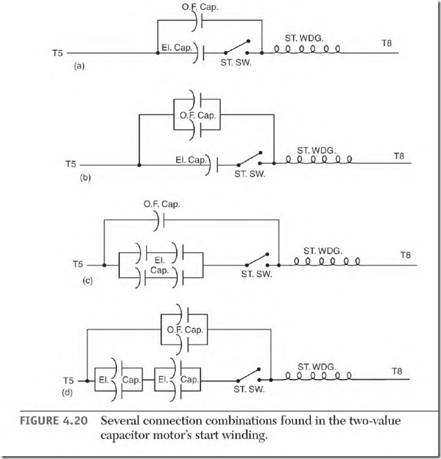
Thro-value capacitor motors (with electrolytic and oil-filled capacitors) use the connections shown in Fig. 4.20. Oil-filled capacitors are always connected in parallel with the electrolytic capacitor and the start switch contacts. If more than one oil-filled capacitor is used, they are always connected in parallel with each other. The voltage rating of the oil-filled capacitor will be two or more times the applied voltage value. Both types of capacitors are found mounted in the motor, on the motor, or remote from the motor.
Power Factor Correcting Winding Figure 4.21 shows a schematic of a special winding in series with an oil-filled capacitor. This winding is wound
on top of the start winding and connected so their polarities are the same. Its purpose is to correct the power factor of the motor.
High-Voltage Problems of the Two-Value Capacitor Motor If the twovalue capacitor motor is connected to a coasting load (such as a radial arm saw), voltage as high as 1500 volts is generated in the motor’s circuitry. (A magnetic interaction between the rotor cage, the closed circuit of the start and run windings, and the oil-filled capacitor creates the high voltage.) The power value of the high voltage is very low, but it can destroy or damage electronic components or anything connected in the motor’s circuitry.


