Objectives
After studying this unit, the student will be able to:
• Describe the Hall effect
• Discuss the principles of operation of a Hall generator
• Discuss applications in which Hall generators can be used
PRINCIPLES OF OPERATION
The Hall effect is a simple principle that is widely used in industry today. The Hall _effect was discovered by Edward H. Hall at Johns Hopkins University in 1879. Mr. Hall originally used a piece of pure gold to produce the Hall effect, but today a piece of semiconductor material is used because semiconductor material works better and is less expensive to use. The device is often re ferred to as the Hall generator.
Figure 25-1 illustrates how the Hall effect is produced. A constant current power supply is connected to opposite sides of a piece of semicon ductor material. A sensitive voltmeter is connected to the other two sides. If the current flows straight . through the semiconductor material, no voltage is produced across the voltmeter connection.
Figure 25-2 shows the effect of bringing a magnetic field near the semiconductor material. The magnetic field causes the current flow path to be deflected to one side of the material. This causes a potential or voltage to be produced across the opposite sides of the semiconductor material.
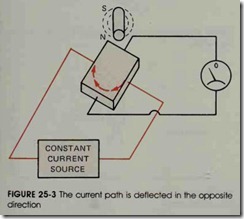
If the polarity of the magnetic field is re versed, the current path is deflected in the oppo site direction as shown in figure 25-3. This causes the polarity of the voltage produced by the Hall generator to change. Two factors determine the polarity of the voltage produced by the Hall gen erator:
1. the direction of current flow through the semiconductor material; and
2. the polarity of the magnetic field used to de flect the current.
The amount of voltage produced by the Hall gen erator is determined by
1. the amount of current flowing through the semiconductor material; and
2. the strength of the magnetic field used to de flect the current path.
The Hall generator has many advantages over other types of sensors. Since it is a solid-state de vice, it has no moving parts or contacts to wear out. It is not affected by dirt, oil, or vibration . The Hall generator is an integrated circuit which is mounted in many different types and styles of cases.
HALL GENERATOR APPLICATIONS
Motor Speed Sensor
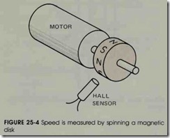
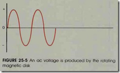
The Hall generator can be used to measure the speed of a rotating device. If a disk with mag netic poles around its circumference is attached to a rotating shaft, and a Hall sensor is mounted near the disk, a voltage will be produced when the shaft turns. Since the disk has alternate magnetic polarities around its circumference, the sensor will produce an ac voltage. Figure 25-4 shows a Hall generator used in this manner. Figure 25-5 shows the ac waveform produced by the rotating disk. The frequency of the ac voltage is proportional to the number of magnetic poles on the disk and the speed of rotation.
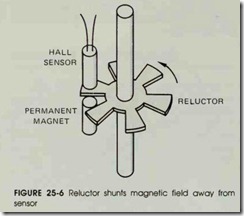
Another method for sensing speed is to use a reluctor. A reluctor is a ferrous metal disk used to shunt a magnetic field away from some other ob ject. This type of sensor uses a notched metal disk attached to a rotating shaft. The disk separates a Hall sensor and a permanent magnet, figure 25-6. When the notch is between the sensor and the mag net, a voltage is produced by the Hall generator. When the solid metal part of the disk is between the sensor and magnet, the magnetic field is shunted away from the sensor. This causes a sig nificant drop in the voltage produced by the Hall generator.
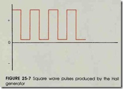
Since the polarity of the magnetic field does not change, the voltage produced by the Hall gen erator is pulsating direct current instead of alter nating current. Figure 25-7 shows the de pulses produced by the generator. The number of pulses produced per second is proportional to the num ber of notches on the reluctor and the speed of the rotating shaft.
Position Sensor
The Hall generator can be used in a manner similar to a limit switch. If the sensor is mounted beside a piece of moving equipment, and a per manent magnet is attached to the moving equip ment, a voltage will be produced when the magnet moves near the sensor, figure 25-8. The advan tages of the Hall sensor are that it has no lever arm or contacts to wear like a common limit switch, and it can operate through millions of operations of the machine.
Current Sensor
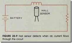
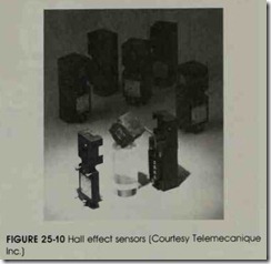
Since the current source for the Hall genera tor is provided by a separate power supply, the magnetic field does not have to be moving or changing to produce an output voltage. If a Hall sensor is mounted near a coil of wire, a voltage will be produced by the generator when current flows through the wire. Figure 25-9 shows a Hall sensor used to detect when a de current flows through a circuit. Hall effect sensors are shown in figure 25-10.
The Hall generator is being used more and
more in industrial applications. Since the signal rise and fall time of the Hall generator is generally less than 10 microseconds, it can operate at pulse rates as high as 100,000 pulses per second. This makes it especially useful in industry.
REVIEW QUESTIONS
1. What material was used to make the first Hall generator?
2. What two factors determine the polarity of the output voltage produced by the Hall generator?
3. What two factors determine the amount of voltage produced by the Hall generator?
4. What is a reluctor?
5. Why does a magnetic field not have to be moving or changing to produce an output voltage in the Hall generator?
