We inferred above that reconnection, after a short supply interruption, could produce current and torque peaks higher than for direct starting or sudden shortcircuit .
Whatever cause would prolong the existence of d.c. decaying currents in the stator (rotor) at high levels would also produce severe current and torque oscillations due to interaction between the a.c. source frequency current component caused by supply reconnection and the large d.c. decaying currents already in existence before reconnection.
One more reason for severe torque peaks would be the phasing between the residual voltage at machine terminals at the moment of supply reconnection. If the two add up, higher transients occur.
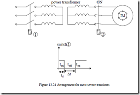
The case may be [13] of an IM supplied through a power transformer whose primary is turned off after starting the motor, at time td with the secondary connected to the motor, that is left for an interval ∆t, before supply reconnection takes place (Figure 13.24).
During the transformer primary turn off, the total (no-load) impedance of the transformer (rts, xt0s), as seen from the secondary side, is connected in series with the IM stator resistance and leakage reactance rs, xls, given in relative (or absolute) units.
To investigate the above transients, we simply use the d–q model in p.u. in (13.83) with the simple motion equation,
H dωr = te − tL (13.109) dt
During the ∆t interval, the model is changed only in the sense of replacing rs with rs + rts and xls with xls + xtos. When the transformer primary is reconnected, rts and xtos are eliminated.
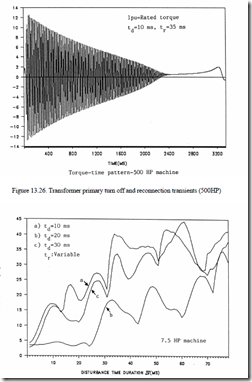
Digital simulations have been run for a 7.5 and a 500 HP IM.
The parameters of the two motors [18] are shown in Table 13.1. Table 13.1. Machine parameters
|
Size HP |
VL line |
rpm |
Tn Nm |
In A |
Rs Ω |
Xls Ω |
Xm Ω |
Rr Ω |
Xlr Ω |
J Kgm2 |
f1 Hz |
|
7.5 |
440 |
1440 |
37.2 |
9.53 |
0.974 |
2.463 |
68.7 |
1.213 |
2.463 |
0.042 |
50 |
|
500 |
2300 |
1773 |
1980 |
93.6 |
0.262 |
1.206 |
54.04 |
0.187 |
1.206 |
11.06 |
60 |
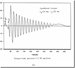
For the 7.5 HP machine, results, as shown in Figure 13.25a, b, c have been obtained. For the 500 HP machine, Figure 13.26 shows only 12 p.u. peak torque while 26 p.u. peak torque is noticeable for the 7.5 HP machine.
Figure 13.27 Peak torque versus perturbation duration (7.5HP machine)
Figure 13.27 shows very high torque peaks. They depend on the turn-off time after starting td. There is a period difference between td values for curves a and c and their behavior is similar. This shows that the residual voltage phasing at the reconnection instant is important. If it adds to the supply voltage, the torque peaks increase. When it subtracts, the peak torques decrease. The periodic behaviour with ∆t is a proof of this aspect.
Also, up to a point, when the perturbation time ∆t increases, the d.c. (nonperiodic) current components are high as the combined stator and secondary transformer (subtransient) and IM time constant is large.
This explains the larger value of peak torque with ∆t increasing. Finally, the speed shows oscillations (even to negative values, for low inertia (power)) and the machine total starting time is notably increased.
Unusually high peak torques and currents are expected with this kind of transients for a rather long time, especially for low power machines while, even for large power IMs, they are at least 20% higher than for sudden short-circuit .
THE ABC−DQ MODEL FOR PWM INVERTER FED IMs
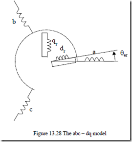
Time domain modeling of PWM inverter fed IMs, both for steady-state and transients, symmetrical and fault conditions, may be approached through the so called abc–dq model (Figure 13.28).
The derivation of the abc–dq model in stator coordinates may be obtained starting again from, abc–arbrcr model with Park transformation of only rotor variables:
 [ ]1 [ ]0
![]() [ ]0 [P3 3× (θ −θb er )] (13.110)
[ ]0 [P3 3× (θ −θb er )] (13.110)
For stator coordinates, θb = 0.
Instead of phase voltages, the line voltages may be used:
Vab, Vbc, Vca instead of Va, Vb, Vc,
Vab = Va −V ; Vb bc = Vb −V ; Vc ca = Vc −Va (13.111)
![]() Making use of the 6 × 6 inductance matrix
Making use of the 6 × 6 inductance matrix ![]() Labca b cr r r (θer ) of (13.1), the
Labca b cr r r (θer ) of (13.1), the
|
abc–dq model equations become |
|
|
[ ] [ ][ ]V = R I +ωrG I[ ]+ L d [ ]I dt |
(13.112) |
|
[ ]R = Diag R ,R ,R ,R ,R ,R[ s s s r r r ] [ ] [V = V ,V ,V ,0,0ab bc ca ] [ ]I = [i ,i ,i ,i ,ia b c dr qr ] 0 0 0 0 0 0 0 0 0 0 |
(13.113) |
0 0 0 0 0
2
3
|
The parameters Ls, Lr, Lm refer to phase inductances, |
|
|
Ls = Lm + L ; Lls r = Lm + Llr The torque equation becomes |
(13.116) |
|
Te = p I1[ ] [ ][ ]T G I Finally, the motion equation is |
(13.117) |
|
J dωr = Te −Tload −Bωr |
(13.118) |
p1 dt
For PWM excitation and mechanical steady-state (ωr = const.) based on Vab(t), Vbc(t), Vca(t) functions, as imposed by the corresponding PWM strategy, the currents may be found from (13.112) under the form
[ ]I• = −[ ] [[ ]L −1 R +ωr [ ]][ ] [ ] [ ]G I + L −1 V (13.119)
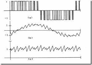
Figure 13.29 Computed waveforms for sinusoidal PWM scheme (Fnc = 21), f = 60 Hz
a.) line to line voltage Vab, b.) line current ia, c.) developed torque
Initial values of currents are to be given for steady-state sinusoidal supply and the same fundamental.
Although a computer program is required, the computation time is rather low as the coefficients in (13.119) are constant.
Results obtained for an IM with Rs = 0.2Ω, Rr = 0.3Ω, Xm = 16Ω, and Xr = Xs = 16.55Ω, fed with a fundamental frequency fn = 60 Hz, at a switching frequency fc = 1260 Hz and sinusoidal PWM, are shown in Figure 13.29. [19]
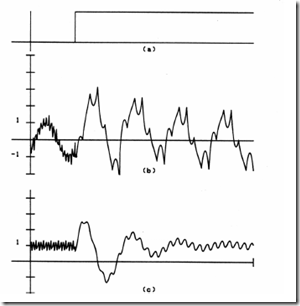
When the speed varies, the PWM switching patterns may change and thus produce current and torque transients. A smooth transition is needed for good performance. The abc–dq model, including the motion equation, also serves this purpose (for example, switching from harmonic elimination PWM (N = 5) to square wave, Figure 13.30 [19].)
Figure 13.30 Computed transient response for a change from harmonic (N = 5) elimination PWM to square wave excitation at 60 Hz
a.) voltage, b.) current, c.) torque
The current waveform changes to the classic six-pulse voltage response after notable current and torque transients. a.) Fault conditions
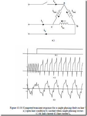
Open line conditions or single phasing due to loss of gating signals of a pair of inverter switches are typical faults. Let us consider delta connection when line a is opened (Figure 13.31a). The relationships between the system currents [iab, ibc, ica, id, iq] and the “fault” currents ibac, ibc, id, iq are (Figure 13.31a).
The voltage relationship is straightforward as power has to be conserved:
VVVbacbc = [ ]C T VVVcabcab ; V[ n ] [ ] [= C T V0 ] (13.122)
Vdq VVdq
Now we may replace the voltage matrix in (13.112) to obtain
[Vn ] [ ] [ ][ ][ ] [ ]= C T R C In + C T ωr [ ][ ][ ] [ ] [ ][ ]G C In + C T L C d Idt[ ]n (13.123)
![clip_image001[4] clip_image001[4]](http://machineryequipmentonline.com/electric-equipment/wp-content/uploads/2017/04/clip_image0014_thumb7.gif)
