Nature of Response and Directional Characteristics
Pressure microphones are those where only one side of the diaphragm is exposed to the actuating sound field. Such devices are basically insensitive to the direction of the arriving sound as long as the wavelength is large compared with the diaphragm circumference. At high frequencies when the wavelength becomes comparable to or even less than the diaphragm circumference, two directional effects become evident. For sound directly incident on the exposed face of the diaphragm, the partial reflection of the pressure waveform at the diaphragm surface increases the acoustic pressure amplitude over that which would exist in an undisturbed sound field. For sound incident from the rear of the exposed face of the diaphragm, the active face of the diaphragm is in the shadow of the microphone’s housing structure and experiences a pressure less than that of the undisturbed sound field. This front-to-back discrimination can only be avoided by employing physically small microphone structures. This is the reason why measurement microphones often have capsules of ¼ inch diameter or even less.
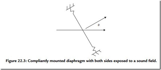
A controlled directional response can be obtained by employing a sensing diaphragm, both faces of which are exposed to the sound field of interest. Such diaphragms experience a driving force that depends on the spatial rate of change of pressure rather than on the pressure itself. Consider the situation shown in Figure 22.3.
Figure 22.3 is a bare bones illustration of a diaphragm stripped of details of the transducing mechanism. Both sides of the diaphragm are exposed to a sound wave that
is propagating along the horizontal axis. The diaphragm may be circular as in a capacitor or moving coil microphone or rectangular as in a ribbon microphone. The principal axis of the microphone is directed perpendicular to the plane containing the diaphragm and, as illustrated, forms an angle θ with the direction of the incident sound. When θ has the value π/2, both faces of the diaphragm experience identical pressures and the net driving force on the diaphragm is zero. Now when θ is 0, the sound wave is incident normally on the diaphragm and the driving force on the left face of the diaphragm will be the pressure in the sound wave at the left face’s location multiplied by the area of the left face.
The diaphragm material, however, is not porous so sound must follow an extended path around the diaphragm along which the sound pressure can undergo a change before reaching the right face. The net driving force on the diaphragm will be the difference in the pressures on the two faces multiplied by the common diaphragm surface area. The pressure difference can be calculated by taking the product of the space rate of change of acoustic pressure, known as the pressure gradient, with the effective acoustical distance separating the two sides of diaphragm. The least value of this distance is the diaphragm diameter in the case of a circular diaphragm.
For a ribbon diaphragm the appropriate value would approximate the geometric mean of the diaphragm’s length and width. Details of a particular microphone housing structure that provide a baffle-like mounting will tend to increase the effective separation. If θ is not zero, the microphone axis is inclined to the direction of the incident sound and the pressure difference is lowered according to the cosine of the angle.
As a first case, consider that the sound source is quite distant from the microphone location so that that the incident sound can be described by a plane wave. The mathematical description of such a wave where the direction of propagation is that of the x axis is
where pm is the acoustic pressure amplitude, ω is angular frequency = 2πf, k is propagation constant = ω/c = 2π/λ, c is phase velocity, and λ is wavelength.
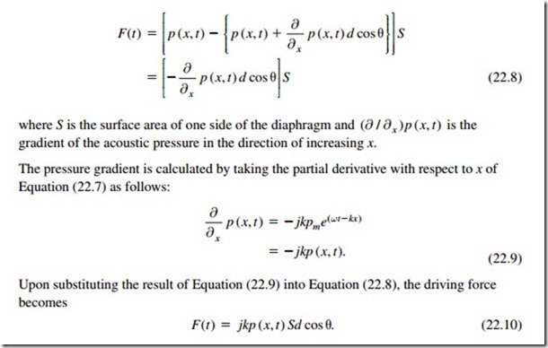
Under this circumstance, the net driving force acting on the diaphragm in the direction of increasing x is given by evaluating the following expressions with x set equal to the coordinate of the diaphragm’s center.
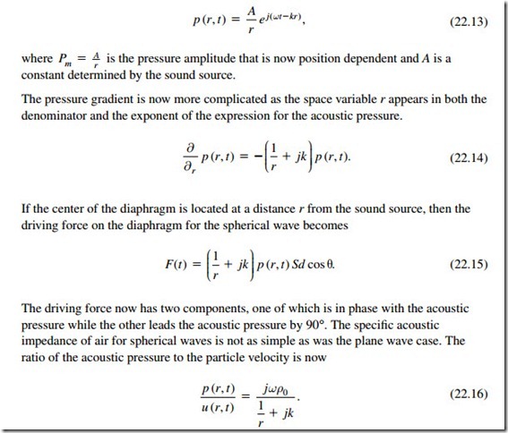
In a given sound wave of normally encountered intensities, a relationship exists between the acoustic pressure and the acoustic particle velocity. The ratio of the acoustic pressure to the particle velocity is called the specific acoustic impedance of air for the wave type in question. This ratio for plane waves is a real number equal to the normal density of air multiplied by the phase velocity of sound. One can then substitute for the acoustic pressure in Equation (22.10) in terms of the particle velocity to obtain an alternative expression for the driving force:
Upon solving Equation (22.16) for the acoustic pressure in terms of the particle velocity and substituting into Equation (22.15), one obtains the very important result
The importance of this result is apparent when Equation (22.17) is compared with Equation (22.8). With the exception of the identity of the space variable, the two equations are identical, implying that pressure gradient microphones respond to the particle velocity in exactly the same fashion whether the incident sound wave is plane, spherical, or a combination of the two. In contrast, pressure-sensitive microphones respond to acoustic pressure whether the source is nearby (spherical case) or distant (plane case). In fact, for a pressure-sensitive microphone the driving force depends only on the acoustic pressure and is given by the direction independent expression
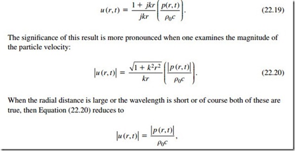
Another very important aspect of pressure gradient microphones is the proximity effect. This phenomenon becomes apparent by a rearrangement of Equation (22.16). This equation is solved for the particle velocity in terms of the pressure and the terms and then multiplied in both numerator and denominator by the radial distance while making use of the fact that k ω/c = to obtain
with the significance that the particle velocity is directly proportional to the acoustic pressure. However, when r is small or the wavelength is large or a combination is true, the reduction becomes
with the significance that the particle velocity varies inversely with frequency. As a consequence, when a sound source is in close proximity to a pressure gradient microphone the lower frequencies of the source produce a larger response than the higher frequencies. This is the basis for the proximity effect.
One final observation regards the directional characteristics of pressure gradient microphones. From Equation (22.15), when θ is in the range π/2 < θ < 3π/2, the cosine of θ is itself a negative quantity and the polarity of the driving force, as well as the electrical output signal of the microphone, is reversed. A use will now be made of this fact in discussing a microphone structure that possesses a variety of several different directional patterns.
A structure consisting of both a pressure gradient microphone element and a pressure microphone element makes possible a microphone possessing adjustable directional characteristics. The elements should individually be small and located close together with the diaphragms of the two elements located in the same plane. A single signal based on a linear sum of the signals from the individual elements is generated by the combination. The root mean square open circuit electrical output of the assembly can be written as
where α is a dimensional constant, β is the fraction of the pressure microphone electrical signal, γ is the fraction of the pressure gradient microphone electrical signal, and θ is the angle of incidence of the acoustic signal.
The fractional signals can be formed and summed through the employment of passive circuitry contained within the microphone housing. The polar response curve of the microphone for a given choice of coefficients is obtained by allowing θ to range continuously from 0 to 2π while plotting the curve where r is the radial distance from the origin and has a maximum value of 1, β and γ are fractional coefficients with β + γ = 1, and θ is the angle of incident sound relative to principal axis of microphone.
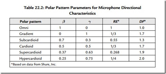
Although β and γ are arbitrary within the constraint that they sum to unity, there are particular values that have proven to be quite useful. This information is listed in Table 22.2.
Some practitioners prefer to employ directional microphones because such microphones respond to reverberant acoustical power arriving from all directions with reduced sensitivity as compared with the same acoustical power arriving along the principal axis of the microphone. This property is expressed by the entry labeled RE in Table 22.2.
RE stands for random efficiency. The hypercardioid pattern, for example, has a random efficiency of ¼. The response to power distributed uniformly over all possible directions is thus only ¼ that for the same total power arriving on axis.
The entry labeled DF in Table 22.2 compares the working distance of a directional microphone to that of an omnidirectional microphone. The DF for a hypercardioid microphone is 2, meaning that the working distance for a source on axis for this microphone can be twice as large as that for an omni in order to achieve the same direct to reverberant sound ratio in the output signal.
These factors when considered alone would lead one to believe that higher gain before acoustic feedback instability would be achievable through the employment of directional
microphones. This is not necessarily the case. As a class, omnidirectional microphones exhibit smoother frequency responses than directional microphones. The frequencies of oscillation triggered by acoustic feedback, the ring frequencies, depend on a number of factors.
Prominent causative agents are peaks in microphone response and peaks in loudspeaker response coupled with antinodes in the normal modes of the room. Room modes at even moderate frequencies can be quite dense. As a consequence, a single peak in either microphone or loudspeaker response may trigger an entire chorus of slightly different ring frequencies. This set of facts would tend to favor omnidirectional microphones over directional ones. The deciding factor is usually not immunity to feedback from the
reverberant field but rather the necessity to reject a nearby source of objectionable sound, including possible strong discrete reflections.
A microphone consisting of a separate pressure and pressure gradient element is quite versatile in that it offers all of the polar response patterns listed in Table 22.2, assuming that it contains the appropriate switch selectable passive circuitry necessary to properly combine the signals from the individual elements. Such a microphone, however, inherently has a shortcoming in that the centers of the two elements are physically offset.
Sound waves incident on the device in other than the principal plane arrive at the two elements at slightly different times. The difference in arrival times introduces a phase difference between the electrical signals generated by the two elements. This phase difference can be significant at high frequencies and can distort the directional response pattern in the high-frequency region. Fortunately, it is possible to avoid the offset problem through the design of a single diaphragm device that also has useful directional characteristics.
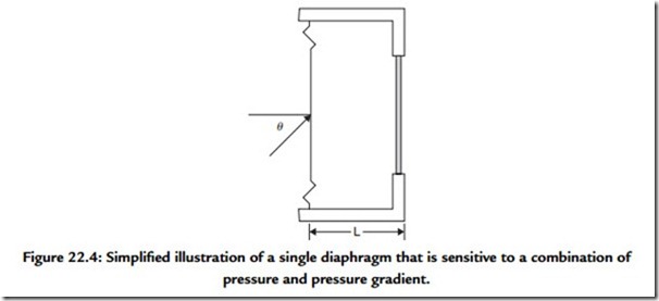
Figure 22.4 is a bare bones illustration of a compliantly mounted diaphragm and a back enclosure that is vented through a porous screen to the external environment. The diaphragm may be part of either a capacitor or moving coil type of transducer, the details of which are not shown for simplicity. A sound wave is incident on the left face of the diaphragm. The direction of the incident wave makes an angle θ with the principal axis of the system. The principal axis is perpendicular to the plane that contains the diaphragm. The acoustic pressure on the left face of the diaphragm assuming a spherical wave is given by
The center of the porous screen to the right of the diaphragm is separated from the corresponding point at the center of the diaphragm by an acoustical distance that amounts to (d + L), where d is the diameter of the diaphragm. We need now to calculate the acoustic pressure at a point just to the right of the center of the porous screen. The acoustic pressure in the incident wave on the diaphragm is a known quantity, p1. As was done in the case of the pressure gradient microphone, we first calculate the rate of pressure change with distance along the direction of propagation. Next, we find the component of this change in the direction of interest. Finally, we multiply this component by the acoustical distance between the points of interest. This last step yields the pressure change. What is desired of course is the pressure at the second point. This is the pressure at the initial point plus the change in pressure. Upon letting p2 represent the acoustical pressure at a point immediately to the right of the center of the porous screen, then
The driving force that actuates the diaphragm, however, is the pressure difference between p1 and the pressure in the cavity to the rear of the diaphragm multiplied by the surface area of one side of the diaphragm. A detailed analysis would show that the pressure in the cavity, pe, depends on both p1 and p2. Recall that for a pressure-sensitive microphone, the diaphragm driving force is directly proportional to the acoustic pressure; whereas for a pressure gradient microphone, it is directly proportional to the gradient of the acoustic pressure.
In the capsule described earlier, the driving force on the diaphragm is proportional to a linear combination of the pressure and pressure gradient terms. The sizes of the coefficients in the linear combination and consequently the particular directional polar pattern hinge on the volume of the cavity, the areas occupied by the diaphragm and the porous screen, the mechanical properties of the diaphragm, and the porosity of the screen. Such microphones are usually constructed having a dedicated directional pattern. The majority of the cardioid family of directional microphones is constructed in this fashion.
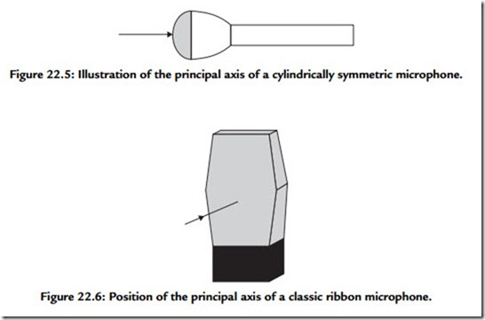
Most microphones have cylindrical symmetry and basically circular diaphragms. The principal axis of such a microphone is centered on the diaphragm, perpendicular to the plane of the diaphragm, and directed along the cylindrical axis, as illustrated in Figure 22.5. The directional polar pattern in a plane is obtained by varying the angle of incident sound relative to the principal axis of the microphone.
The three-dimensional directional response of such a microphone is obtained by revolving the directional polar pattern about the cylindrical axis of the microphone. Ribbon microphones, however, don’t follow the aforementioned rules, as their diaphragms do not possess cylindrical symmetry. Such microphones are usually designed to be addressed from the side, as illustrated in Figure 22.6.
The directional response in the horizontal plane of the depicted ribbon microphone is a figure eight. Revolving this pattern about the principal axis generates two spheres that describe the microphone’s response in three dimensions. The polar directional patterns listed in Table 22.2 are displayed in Figure 22.7A, while the three-dimensional directional response is sketched in Figure 22.7B.
The polar patterns of Figure 22.7A are theoretical ideals and have a linear radial axis consistent with the form of the describing equations. Real microphones fall short of the theoretical ideal in two ways. They never display complete nulls in response and the polar response curves are frequency dependent. Compare the measured polar response curves of a cardioid microphone presented in Figure 22.8 with its counterpart in Figure 22.7A.
Manufacturer’s polar response data are usually presented employing a logarithmic polar axis while excluding a small region in the vicinity of the origin. Such a presentation for yet again a different cardioid microphone is given in Figure 22.9.
In examining Figure 22.9, note that the reference axis has a different orientation and that the radial coordinate represents attenuation expressed in decibels relative to the on-axis value.
