Rochester Carburetors
ONE BARREL CARBURETORS
Models B, BC & BV
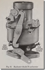
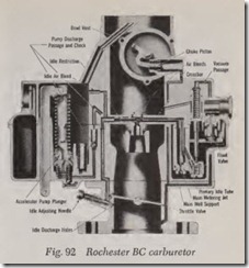
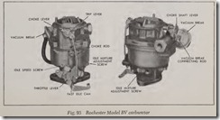
These carburetors are of the same design with Model B equipped with a manually operated choke while Models BC and BV have automatic chokes, Figs. 91, 92 and 93. In addition to the fuel inlet system, the four basic metering systems are used. The distinctive features of these carburetors are:
1. Concentric fuel bowl: Regardless of any shift of fuel level in the bowl the main metering jet is always immersed in fuel.
2. Centrally located main discharge nozzle: A shift in fuel level has little or no effect on the rate of discharge from the nozzle.
3. The main well and support assembly, which contains the main metering jet and the power valve, is attached to the cover and suspended in the float bowl.
4. Twin floats operate the needle valve to control the fuel level.
The description which follows applies to both models except where reference is made to the automatic choke which refers to the BC and BV models.
On the Model BV carburetor, Fig. 93, the choke thermostatic coil is locat ed on the exhaust mani fold and is connected to the choke valve shaft by a connecting rod. The exhaust mounted choke coil provides excellent choke response to supply the correct fuel mixtures to the engine during the w arm -up period. A vacuum diaphra gm unit mounted on the carburetor air horn opens th e choke valve, just after starting, to a point where the cold engine will run without loading or stalling.
Idle System
The idle fuel first passes through the float bowl through the main metering j et attached to the bottom of the m ain well assembly. This fuel is then drawn up the main well by manifold vacuum to the crossbar of the air horn . Air joins the fuel through the air bleeds in the center of the cross bar . This fuel-air mixture is then calibrated as it pa sses through the idle restr iction and is dr awn down the passage in the float bowl to the throttle body. The idle fuel is then metered to the engine by the idle adj usting needle below th e throttle valve.
Part Throttle System
As the throttle valve is opened furth er ( from idle position) air at a higher velocity is drawn down the carburetor throat, and the fuel and air begin to pass from the main discharge nozzle to meet the increased engine demand. Further throttle opening will result in higher fuel flow from the nozzle and decreased flow from the idle system until it eventually cuts out altogether.
Power System
A vacuum -operated power system provides the additional fuel needed for sustained high speed operation or for increased road load power.
A direct manifold passage within the carburetor to the engine intake manifold operates this sys tem. At any manifold vacuum above approxi mately 5 inches of mercury the power actuating piston is held in the “up” position against the compression of the power spring, by manif old vacuum. Thus no fuel passes through the power valve.
In accordance with the principle that any sud den acceleration causes a drop in manif old vacuum, the power spring has been calibrated so that any vacuum below approximately 5 inches of mercury, forces the power actuating piston “down”.
The end of this piston then unseats the spring loaded ball in the power valve. Fuel passes readily around the ball into the base of the main well support. The calibrated power restriction meters
the fuel prior to its joining the fuel from the main metering jet. Conversely, as the manifold vacuum rises above approximately 5 inches of mercury, the power piston is drawn immediately to the “up” position, and the spring-loaded ball of the power valve closes, returning the carburetor to the conomical part throttle mixtures.
The relief passage which is drilled from the bore of the air horn into the power piston passage serves to relieve any vacuum built up around the piston diameter. This vacuum, if umclieved, would draw fuel past the piston and down the vacuum passage into the manifold, resulting in an overly rich mixture.
Accelerating Pump System
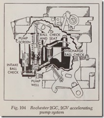
To provide fuel for smooth, quick acceleration, a double spring pump plunger is used. The rate of compression of the top spring versus the bottom spring is calibrated to insure a sustained charge of fuel for acceleration.
To exclude dirt, all fuel for the pump system first passes through the pump screen in the bot tom of the float bowl. It is then drawn past the ball check into the pump well on the intake stroke of the plunger. Upon acceleration, the force of the pump plunger seats th e ball check and forces fuel up th e discharge passag e. The pressure of the fuel lifts the pump outlet ball check from its seat. The fuel is tlren sprayed on the edge of the venturi by the pump jet and delivered to th e engine.
The pump plunger head has been designed to eliminate fuel percolation in the pump system. When the engine is not operating, any build-up of fuel vapors in the pump will rise and by-pass the vent ball. This allows th e hot fuel and vapors to circulate up the passa ge in the plunger head and return to the float bowl. Without this feature, any vapor pressure build-up would evacuate the fuel in th e pump system into the intake manifold, causing poor initial acceleration due to lack of fuel in the pump system as w ell as difficult hot weather starting.
Choke System
The automatic ch oke is the conventional bi metal th ermostatic spring type and functions in the same m anner as described for Carter carbu retors.
Model H, 1960–61 Corvair
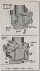
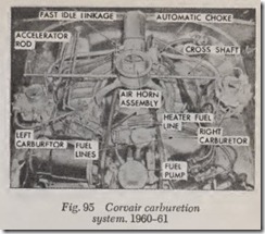
The Corvair engine for 1960-61 uses two of these carburetors, one on each intake manifold, Figs. 94 and 95. The choke is positioned in the centrally located air horn assembly at the top of the engine. From the air cleaner, two air tubes direct filtered air to the top of each carburetor. The two carburetor throttle shaft levers are con nected by a cross shaft which is actuated by the accelerator linkage. The air horn assembly, while separated from the carburetors, is nevertheless a definite part of the carburetion system. Outside air passes through the air horn, through the air cleaners and arrives as clean filtered air at each carburetor. The automatic choke, choke modifier and fast idle linkage are located on the air horn assembly and are controlled by the same cross shaft which operates the carburetors.
This carburetor is fundamentally the same design as the Rochester Model B, utilizing the same basic fuel metering systems.
Model HV, 1962-1966 Corvair
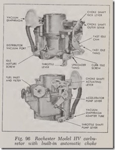
These engines use two identical carburetors of the type shown in Fig. 96, with built-in automatic choke. The set-up differs from earlier models in that the choke no longer is mounted in the cen trally located air horn. The automatic choke mechanism consists of a thermostatic control coil mounted to the lower side of the cylinder head, linked directly to the carburetor choke valve shaft, and a vacuum diaphragm mounted on the air horn.
Models M & MV
Called the Monojet, this carburetor is a single· bore downdraft instrument which employs triple concentric venturis in conjunction with a refined metering system that improves mixture control and performance.
A plain tube nozzle is used with the multiple venturi arrangement. Fuel How to the nozzle from the main metering system is controlled by a mechanically and vacuum operated variable ori£ce jet. On the mechanical side, a specially tapered rod operates in the £xed ori£ce of the main metering jet and is connected directly by linkage to the main throttle shaft. A vacuum oper ated enrichment system is used in addition to provide good performance during moderate to heavy acceleration. The main metering system also has an adjustable How feature, provided to correct the slight variations that occur during normal production of the components.
Idle System
A separate and adjustable idle system is used in conjunction with the main metering system to meet fuel requirements during idle and low speed operation. It incorporates a vertical slot design off idle discharge port to provide a good transition between idle and main metering system operation. On some Monojet carburetors a hot idle compen sator is added to maintain smooth engine idle during periods of prolonged hot engine operation.
Choke System
These carburetors are designed so that either an automatic or manual choke can be £tted. A con ventional choke valve is located in the air horn bore. On automatic choke models, the vacuum diaphragm unit is an integral part of the air hom and the choke coil is remotely mounted on the intake manifold. The -conventional bi-metallic spring coil is connected to the choke shaft by linkage. Extra enrichment is provided on auto matic choke models during cold start by a special feature which allows use of low torque thermo static coils for increased fuel economy.
TWO BARREL CARBURETORS
Models 2GC, 2GV
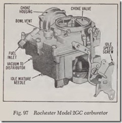
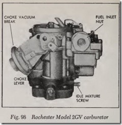
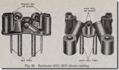
Model 2GC, Fig. 97 and 2GV, Fig. 98 are two barrel units of the calibrated cluster design, Fig.99. The cluster casting embodies the small or secondary venturi, the high speed passages, the main well tubes and nozzles, the idle tubes, and the calibrated air bleeds for both the low and high speed metering systems, as well as the accelerat ing pump jets.
The cluster £ts on a platform provided -in the body casting of th e carburetor so that the main well and idle tubes are suspended in the fuel.
This method of design and assembly serves to insulate the main well tubes and idle tubes from engine heat, thus preventing heat expansion and percolation spill-over during hot idle periods of operation and during the time the hot engine is not operating.
An external vent with a protective cover to keep out dirt is located in the center of the bowl cover to provide adequate venting of the unit under all types of operating conditions. No internal tube venting methods are used.
Float System
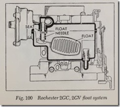
Fig. 100. Entering fuel first travels through the inlet strainer to remove foreign particles which might block jets or passages. Then the fuel passes through the needle and seat into the carburetor bowl. As in all carburetors, the fuel flows into the bowl until the rising liquid level raises the float to a position where the valve is closed. The float tang prevents the float from traveling too far down ward.
Idle System
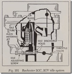
Fig. 101. In the curb idle speed position, the throttle valve is opened slightly, allowing a small amount of air to pass through between the wall of the carburetor and the edge of the throttle valve.
Fuel is drawn from the fuel bowl through the main metering jets into the main well. It is metered by the idle fuel metering orifice at the lower tip of the idle tube and travels up the idle tube. When the fuel reaches the top of the idle tube, it mixes with air drawn through the primary idle air bleed (the larger of the two holes on top of the cluster, Fig. 99) and the mixture moves through the horizontal idle passage.
The smaller of the two holes on top of the cluster is the secondary idle air bleed, through which more air enters and combines with the mixture.
The fuel-air mixture next moves down the verti cal idle passage to the three idle discharge holes located just above the throttle valve. Th rough these holes additional air is added to the mixture, which then passes through the idle needle hole.
In addition to this mixture of fuel and air, there is air entering the bore through the slightly open throttle valve. The position of the idle adjus tment needle governs the amount of fu el-air mixture admitted to the carburetor bore, the same as in all carburetors under discussion.
Part Throttle System
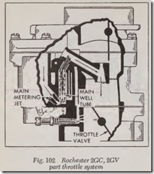
Fig. 102. Opening of th e throttle valve progres sively exposes the three idle discharge holes to manifold vacuum and th e air stream with the result that they deliver additional fuel-air mixture for f ast idle engine requir ements.
As the throttle is opened still further, a greater air velocity passes through the carburetor, the fuel flows throu gh the main · meterin g system and de creased –flow from th e idle system until it eventu ally cuts out altogether.
Power System
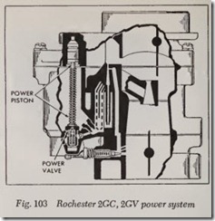
Fig. 103. A spring-loaded power piston, con trolled by vacuum , regulates th e power valve to supply additional fuel according to engine speed and load. The power piston vacuum channel is open to manifold vacuum beneath the throttle valves; thus the vacuum in the channel rises and falls with manifold vacuum.
During idle and part throttle operation, the manifold vacuum in the channel is normally high enough to hold the power piston in the fully raised position against the tension of the spring. As the manifold vacuum drops with load, the calibrated spring forces the piston down against the power valve, to open and allow additional fuel flow through the calibrated power restrictions into the main wells.
A two-step valve allows a gradual increase in fuel flow as the power valve is opened. At full throttle position, the power valve is fully opened to permit maximum calibrated fuel flow from the power system.
As the load decreases, manifold vacuum in creases. The increasing vacuum pull on the piston gradually overcomes the spring tension and re turns the power piston to its original raised posi tion, with the valve fully closed.
Accelerating Pump System
Fig. 104. This system functions in the same manner as described for Model B and BC carbu retors.
Choke System
As with conventional built-in automatic chokes, the system used with this carburetor includes a thermostatic coil, housing, choke piston, choke valve, and a fast idle cam and linkage. It is controlled by a combination of intake manifold vacuum, air velocity against the offset choke valve, atmospheric pressure and hot air from the choke stove. It functions in much the same man ner as Carter carburetor chokes.
The Model 2GV carburetor is also an automatic choke model but the thermostatic coil is located on the manifold and is connected to the choke valve by linkage. A vacuum break is used to open the choke valve to a point where the engine will operate without stalling or loading up after the engine is started.
FOUR BARREL CARBURETORS
Modei4GC
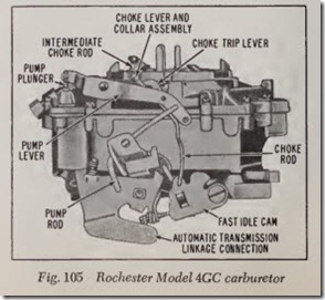
Model 4GC, Fig. 105, is essentially two 2GC carburetors in a single casting. The “Primary Side” of the carburetor contains all the conventional systems (float, idle, part throttle, power, pump and choke). The “Secondary Side” supplements the primary side with separate float and power systems.
