LENZ’S LAW
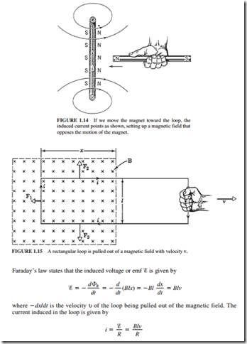
Lenz’s law states that the induced current will be in a direction that opposes the change that produced it. If a magnet is pushed toward a loop as shown in Fig. 1.14, an induced cur- rent will be established in the loop. Lenz’s law predicts that the current in the loop must be in a direction such that the flux established by it must oppose the change. Thus, the face of the loop toward the magnet must have the north pole. The north pole from the current loop and the north pole from the magnet will repel each other. The right-hand rule indicates that the magnetic field established by the loop should emerge from the right side of the loop. Thus, the induced current must be as shown. Lenz’s law can be explained as follows: When the magnet is pushed toward the loop, this “change” induces a current. The direction of this current should oppose the “push.” If the magnet is pulled away from the coil, the induced cur- rent will create the south pole on the right-hand face of the loop because this will oppose the “pull.” Thus, the current must be in the opposite direction to the one shown in Fig. 1.14 to make the right-hand face a south pole. Whether the magnet is pulled or pushed, its motion will always be opposed. The force that moves the magnet will always experience a resisting force. Thus, the force moving the magnet will always be required to do work.
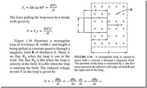
Figure 1.15 shows a rectangular loop of width l. One end of it has a uniform field B pointing at a right angle to the plane of the loop into the page (0 indicates into the page and 0 out of the page). The flux enclosed by the loop is given by
where R is the loop resistance. From Lenz’s law, this current must be clockwise because it is opposing the change (the decrease in cJB). It establishes a magnetic field in the same direction as the external magnetic field within the loop. Forces F2 and F3 cancel each other because they are equal and in opposite directions. Force F1 is obtained from the equation (F = i l X B)
where dcJB/dx is the slope of the curve shown in Fig. 1.17a.
clockwise. There is no voltage induced in the coil when it is entirely in the magnetic field because the flux cJB through the coil does not change with time. Figure 1.17c shows the rate P of thermal energy generation in the loop, and P is given by
If a real magnetic field is considered, its strength will decrease from the center to the peripheries. Thus, the sharp bends and corners shown in Fig. 1.17 will be replaced by smooth curves. The voltage � induced in this case will be given by max sin wt (a sine wave). This is exactly how ac voltage is induced in a real generator. Also note that the prime mover has to do significant work to rotate the generator rotor inside the stator.

