Magnetic Contactors
A contactor may be defined as a device, operated other than by hand, for repeatedly establishing and interrupting an electric power circuit. Contactors are employed in control, as well as in power circuits, and as single units or in groups, with load currents on the main contacts ranging from fractions of an ampere to thousands of amperes, depend ing on the particular application.
Although the construction of a contactor is similar to that of a circuit breaker, its action is the exact opposite. A circuit breaker usually employs an electromagnet for its opening when a fault occurs, whereas a contactor employs an electromagnet for opening or closing a circuit under normal operating conditions. Thus, a contactor is never designed to operate on short -circuit currents. This function is delegated to circuit breakers or fuses, as the case may be.
INTERLOCKS
There are two main types of interlocks usually incorporated in magnetic contactors, and they are named according to their function:
1. Electrical inter locks,
2. Mechanical inter locks.
Electrical Interlocks
Electrical interlocking generally consists of a system of wtnng whereby, when one of the interlocked devices is operating, the control circuit to a second device cannot be completed; or the wiring may be such that the second device or starter cannot be energized until the first device or starter has been put into operation . This is accomplished by auxiliary circuit devices known as electrical interlocks, which are open or closed as the device upon which they are used is operated. By definition, an electrical interlock is a device which is actuated by the operation of some other device (usually the main contactor) with which it is directly associated to govern succeeding operations of the same or some allied device.
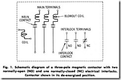
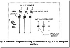
Electrical interlocks (sometimes called auxiliary con/actors) function as a result of the movement of the main contacts of the contactor to which they are mechanically connected. Thus, when the main contacts are closed, one or more of the electrical interlocks may be in the open position, and one or more in the closed position. On the other hand, when the main contacts are opened, the interlock contacts which were formerly in the open position will now be closed, and vice versa. (See Figs. 1 and 2.)
Electrical interlocks are usually termed normally closed (NC) and normally open (NO), depending on their function in the circuit they operate. This terminology refers to the position of the contacts of the interlock when the main contacts of the contactor are in a de-energized or non operated position.
Mechanical Interlocks
This type of interlocking may be defined as a mechanical arrangement whereby one of the interlocked devices is mechanically prevented from functioning when the other is energized. In certain applications it is necessary to prevent one contactor from closing when a second contac tor is closed. In order to prevent this, a mechanical interlock consisting of a piece of metal is hinged at the center and arranged in such a way that, when both contactors are in the open position, the center piece is in the neutral position. Closing one contactor causes it to strike one end of the interlock, moving it toward the panel, thus causing the other end of the interlock to take such a position as to prevent the closing of the second contactor.
A common type of mechanical interlocking is that associated with doors of enclosures housing high-voltage control apparatus, whereby the door cannot be opened while the contactor or circuit breaker is in the energized position. Electrical and mechanical interlocking are both frequently used in the same device, one of the best examples being an ac reversing motor starter.
SHADING COILS
The magnetic structure in an ac contactor must be laminated to reduce core losses, whereas the magnetic structure in a de contactor is of solid material. Another difference between the two types of contactors is that the ac type produces a distinct hum or chattering, pitched at twice the frequency of the circuit, whereas the de contactor is entirely noiseless.
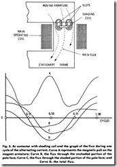
The chattering effect is usually reduced to a mtntmum in an ac contactor by the use of apole shader or shading coil. A pole shader may be defined as a short-circuitedcoil embedded in one or both pole faces of an ac magnet. Its function is to divide the pole faces (Fig. 3) so that only a part of the flux links the short-circuited turn, with the result that the flux from each part of the pole face will exert an independent holding force on the contactor armature. The resistance and reactance of the shading coil are in such proportion that the induced current in the coil is out of phase with the main flux. Thus, the pull on the armature can be maintained without the pulsating effect caused by the normal ac fre quency.
De magnets operated from solid-state rectifiers are commonly used on the larger sizes of ac contactors. This makes it possible to use a solid magnetic structure rather than one that is laminated. When this method is used, all troubles incidental to pole shaders, as well as the disturbing ac hum, are eliminated. This method also results in reduced power consumption in the magnet coil, and a longer contactor life.
ARC SUPPRESSION
An electric arc is a discharge of electricity between electrodes. In order for an arc to be established between the electrodes, it is essential that there be a surrounding medium of gas or vapor.
Magnetic Blowout
The various manufacturers of electrical contactors, have conducted considerable research which has resulted in great improvements, espe cially in the field of arc extinguishing, resulting in more effective contactors and a substantial saving in material and space requirements.
Since an arc occurs between two contactor tips as they open on normal operation, heating and burning of the tips occur. It is therefore highly desirable to extinguish the arc as quickly as possible and to keep it from hanging on any one part of the tip surface where the heating would be concentrated. When relatively small currents are being con trolled, the tip can be opened sufficiently to stretch the arc, so that it is quickly extinguished. Double-break tips which give the same length of gap with only one-half the travel of the movable tip on a single-break device are also employed for fast extinction of the arc. Double-break tips have an added advantage in that no flexible shunts are requjred as on a single-break contactor.
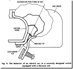
When it is desired to employ a contactor for interruption of heavier current, blowout coils and arc chutes are used to produce a long arc in a relatively small space . The blowout coil is mounted so that its magnetic field is in the path of the arc. The coil is connected in series with the contactor itself so that the motor current flows through the coil as long as the contactor is closed or as long as there is an arc between the contacts. The field set up by the blowout coil magnetically repels the arc upward, as in Fig. 4, and quickly stretches it within the arc chute to such a length that it is extinguished. The extinction is assisted by the cooling action of the restricted section of the arc chutes. The blowout coil is used effectively on most contactors carrying a current of 25 amperes or more, and where it is desirable to interrupt the circuit as rapidly as possible.
Deion Arc Quenching
Until quite recently, the principal method employed in contactor arc extinction in both ac and de circuits was the use of magnetic blowouts. Here, the arc is extinguished by a powerful blowout field and by stretching the arc across arc splitters, thereby lengthening it until instability and extinction occur . In ac circuits where it is required to interrupt large amounts of current, however, the breaker structure must be relatively large, and special precautions must be observed to keep the arc within the limits of safety.
The deion type of contactor has been designed as a result of the continued demand for a contactor of increased interrupting and current capacity for use in small enclosures. The word “deion” has been coined to designate any type of arc-extinguishing apparatus which functions by rapidly restoring the insulating properties of air or gases in which it operates, by means other than simply stretching or cooling the arc. By the use of a properly designed deionizing chamber, the arc may be extinguished in a relatively small space, and the gases associated with the arc allowed to escape from the deionizing chamber only after being rendered nonconductive and harmless.
The elimination of the magnetic blowout coil also decreases the heat losses produced in the blowout structure, permitting the current-carry ing parts to operate cooler, which permits a reduction in the size of the enclosure for a given temperature rise. The deion type of contactor thus makes it possible to have a more compact line starter, more tightly enclosed, with a higher rating, and capable of performing more difficult tasks than those built conventionally.
SHUNT CONTACTORS
A shunt contactor is one which is operated by a shunt coil energized from a constant-voltage power source. For de operation, such contac tors are usually of the single- or double-pole type.
A single-pole shunt contactor is suitable for the remote control of circuits carrying large currents and for the full-voltage control of small motors. The are also used extensively for the control of miscellaneous de circuits in such applications as industrial heating, battery charging, control interlocking, and others. When used with such accessories as float switches, pressure governors, push-button stations, etc., they provide under voltage protection or release, depending on the contact arrangement of the accessory used.
The single-pole contactor consists of a front-connected contactor mounted on a compound base that is usually equipped with feet for wall mounting. The magnet frame consists of a steel casting, with the coil mounted on a steel core.
The circuit for a push-button-operated single-pole contactor is shown in Fig. 5, and a double-pole type in Fig. 6. With the coil deenergized, the contactor is in its normal, or open, position. When the push button is pressed, the coil attracts the movable armature to the stationary core, thus closing the contactor. The stationary contact is provided with a sizable arc shield or horn which serves to limit the arc and direct it upward and away from the contacts. The movable contact has a heavy, flexible cable connected to an independent stud through the insulating base, thus avoiding the necessity of carrying the current through the steel frame of the contactor.
LOCKOUT CONTACTORS
Lockout contactors are used principally as a means of obtaining current-limit acceleration on de motors. Such contactors for motor control are constructed so that the contacts will not close until the circuit current has dropped below a definite value. They are made in two general forms:
1. . The single coil,
2. The double coil.
The single-coil type is usually referred to as a series contactor, while the two-coil type is called a series lockout contactor. Both of these types, however, possess the lockout feature of the contactor; that is, they are held open until the current has dropped to some definite value.
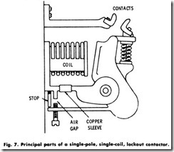
The general principle of operation of the single-coil type can be better understood by referring to Fig. 7. The current passing through the operating coil produces a magnetic field which takes two paths. One path is through the core of the coil, through a section of the restricted area surrounded by the copper sleeve, through the armature and the main air gap, and back to the core of the coil. The other path is through the core of the coil, down through the adjustable air gap, through the tail of the armature, and through the armature and main air gap back to the core of the coil.
When no current is passing through the coil, the armature is in the open position. When a large current is passing through, the magnet field becomes so strong that the path surrounded by the copper sleeve becomes saturated so that the flux through this part cannot exceed a certain amount. The magnetic flux through the adjustable air gap will vary with the current through the operating coil, and this path will not become saturated.
Any flux passing across the adjustable air gap produces an attracting force on the tail of the armature. This force tends to hold the armature open against the closing force exerted between the core of the coil and main part of the armature. As the current decreases in value, the flux across the adjustable air gap also decreases, and thus the holding-out force on the tail of the armature is reduced.
After the current has decreased to a certain value (determined by the setting of the adjustable air gap), the holding-out force on the tail of the armature is not sufficient to overcome the closing force exerted by the core of the coil on the main part of the armature, and the contactor closes.
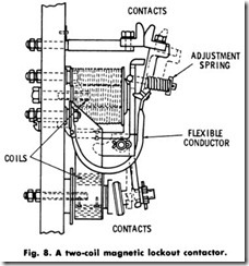
In the two-coil type of series contact or (Fig. 8), two coils are connected in series with each other and with the circuit to be controlled. The armature is pi voted so that the larger coil acts upon one side of the armature with a force that tends to close the contactor. The smaller coil acts on the other side of the armature with a force that tends to hold the contactor open. The areas of the magnetic circuits are so designed that the force tending to close the contactor remains practically constant, regardless of the amount of current, while the force tending to hold the contactor open varies with the current. Therefore, after the current has decreased to a certain value, the holding-out force is not sufficient to overcome the closing force, and the contactor closes. The air gap of the locking-out circuit can be adjusted so that the current above which the contactor holds open can be adjusted over a wide range.
