Objectives
After studying this unit, the student will be able to:
• State several advantages of the use of a clutch in a drive
• Describe the operating principles of magnetic clutches and drives
• Distinguish between single and multiple-face clutches
• Connect magnetic clutch and magnetic drive controls
• Recommend troubleshooting solutions for magnetic clutch and drive problems
ELECTRICALLY CONTROLLED MAGNETIC CLUTCHES
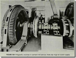
Machinery clutches were originally designed to engage very large motors to their loads after the motors had reached running speeds, figure 58-1. Clutches provide smooth starts for operations in which the material being processed might be dam aged by abrupt starts, figure 58-2. Clutches are also used to start high-inertia loads, since the starting may be difficult for a motor that is sized to handle the running load. When starting condi tions are severe, a clutch inserted between the mo tor and the load means that the motor can run within its load capacity. The motor will take longer to bring the load up to speed, but the mo tor and load will not be damaged.
As more automatic cycling and faster cycling rates are being required in industrial production, electrically controlled clutches are being used more often.
Single-face Clutch
The single-face clutch consists of two discs: one is the field member (electromagnet) and the other is the armature member. The operation of the clutch is similar to that of the electromagnet in a motor starter, figure 58-3. When current is applied to the field winding disc through collector (slip) rings, the two discs are drawn together mag netically. The friction face of the field disc is held tightly against the armature disc to provide posi tive engagement between the rotating drives. When the current is removed, a spring action sep arates the faces to provide a definite clearance be tween the discs. In this manner, the motor is me chanically disconnected from the load.
Multiple-face Clutch
Multiple-face clutches arc also available. In a double-face clutch, both the armature and field discs are mounted on a single hub with a double faced friction lining supported between them. When the magnet of the field member is ener gized, the armature and field members are drawn together. They grip the lining between them to provide the driving torque. When the magnet is de-energized, a spring separates the two members and they rotate independently of each other. Dou ble-face clutches are available in sizes up to 78 inches in diameter.
A water-cooled magnetic clutch is available for applications that require a high degree of slip page between the input and output rotating mem bers. Uses for this type of clutch include tension control (wind-up and payoff) and cycling (starting and stopping) operations in which large differ ences between the input and the output speeds are required. Flowing water removes the heat gener ated by the continued slippage within the clutch. A rotary water union mounted in the end of the rotor shaft means that the water-cooled clutch can not be end-coupled directly to the prime mover. Chains or gears must be used.
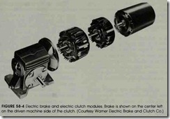
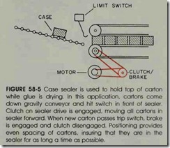
A combination clutch and magnetic brake disconnects the load from the drive and simulta neously applies a brake to the load side of the drive. Magnetic clutches and brakes are often used as mechanical power-switching devices in module form. Figure 58-4 shows a drive line with an elec tric clutch (center right) and an electric brake. An application of this arrangement is shown in figure 58-5. Remember that the quicker the start or stop, the shorter the life of this equipment.
Magnetic clutches are used on automatic ma chines for starting, running, cycling, and torque limiting. The combinations and variations of these functions are practically limitless.
MAGNETIC DRIVES
The magnetic drive couples the motor to the load magnetically. The magnetic drive can be used as a clutch and can be adapted to an adjustable speed drive.
The electromagnetic (or eddy current) coupling is one of the simpler ways to obtain an adjustable output speed from the constant input speed of squirrel cage motors .
There is no mechanical contact between the rotating members of the magnetic drive. Thus, there is no wear. Torque is transmitted between the two rotating units by an electromagnetic reac tion created by an energized coil winding. The slip between the motor and load can be controlled con tinuously, with more precision, and over a wider range than is possible with the mechanical friction clutch.
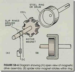
As shown in figure 58-6, the magnet rotates within the steel ring or drum. There is an air gap between the ring and the magnet. The magnetic flux crosses the air gap and penetrates the iron ring. The rotation of the ring with relation to the magnet generates eddy currents and magnetic fields in the ring. Magnetic interaction between the two units transmits torque from the motor to the load. This torque is controlled with .a rheostat which manually or automatically adjusts the direct current supplied to the electromagnet through the slip rings.
When the electromagnetic drive responds to an input or command voltage, a further refine ment can be obtained in automatic control to reg ulate and maintain the output speed. The mag netic drive can be used with any type of actuating device or transducer that can provide an electrical signal. For example, electronic controls and sen sors that detect liquid level, air and fluid pressure, temperature, and frequency can provide the input required.
A tachometer generator provides feedback speed control in that it generates a voltage that is proportional to its speed. Any changes in load condition will change the speed. The resulting generator voltage fluctuations are fed to a control circuit which increases or decreases the magnetic drive field excitation to hold the speed constant.
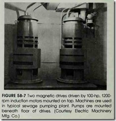
For applications were a magnetic drive meets the requirements, an adjustable speed is fre quently a desirable choice. Magnetic drives are used for applications requiring an adjustable speed, such as cranes, hoists, fans, compressors, and pumps, figure 58-7.
REVIEW QUESTIONS
1. How is the magnetic clutch engaged and disengaged?
2. What devices may be used to energize the magnetic clutch?
3. Which type of drive is best suited for maintaining large differences in the input and output speeds? Why?
4. What is meant by feedback speed control?
5. How is the magnetic drive used as an adjustable speed drive?
