INTRODUCTION
This section provides information on electric control circuits used in heating, ventilating, and air conditioning systems. Electric energy is commonly used to transmit the measurement of a change in a controlled condition from a controller to other parts of a system and to translate the change into work at the final control element. For these purposes, electricity offers the following advantages:
– It is available wherever power lines can be run.
– The wiring is usually simple and easy to install.
– The signals received from sensing elements can be used to produce one or a combination of electro-mechanical outputs. For example, several actuators can be controlled from one controller.
– Single controller-actuator combinations are possible without the need for a main-air source as in pneumatic
control.
Electric controls consist of valve/damper actuators, temperature/pressure/humidity controllers, relays, motor starters and contactors. They are powered by low or line voltage, depending on the circuit requirements. Controllers can be wired to perform either primary or limit functions (high or low limit). Electric actuators can be two position or proportioning and either spring return or nonspring return.
The information in this section is of a general nature and intended to explain electric control fundamentals. There are places where Honeywell nomenclature is used, such as R, W, B, for wiring terminals and Series 40 through 90 for classifying control circuits. These may vary with controls of a different manufacturer.
DEFINITIONS
Actuator: A device used to position control dampers and control valves. Electric actuators consist of an electric motor coupled to a gear train and output shaft. Typically, the shaft drives through 90 degrees or 160 degrees of rotation depending on the application. For example, 90-degree stroke actuators are used with dampers, and 160-degree stroke actuators are used with valves. Limit switches, in the actuator, stop the motor at either end of the stroke or current limiters sense when the motor is stalled at the end of the stroke. Actuator gear trains are generally factory lubricated for life so no additional lubrication is necessary.
Actuators may attach to the valve stem or damper shaft through a linkage or be direct coupled connecting directly to the stem or shaft.
In some actuators the motor is electrically reversible by the controller. A Solenoid brake is commonly used on spring-return actuators to hold the actuator in the control position. Some actuators have a return spring which enables the output shaft to return to the normal position on loss or interruption of power. Most two- position actuators drive electrically to the control position and rely on only the spring to return to the normal position. Spring-return actuators have approximately one-third the output torque of comparable non-spring-return actuators since the motor must drive in one direction against the return spring. A return-to-normal position on power failure
function maybe provided by an integral rechargeable battery, capacitor, or constantly wound spring so that there is no reduction in operating force.
The direction of shaft rotation on loss of power varies by model for spring-return actuators. The direction can be clockwise (cw) or counterclockwise (ccw) as viewed from the power end of the actuator. Actuator controlled valves and dampers also vary as to whether they open or close on a loss of power. This depends on the specific actuator, linkage arrangement, and valve or damper selected. Because of these factors, the terms cw/ccw or open/close as used in this literature are for understanding typical circuits only and do not apply to any particular model of actuator.
Actuators are available with various timings to drive through full stroke such as 15, 30, 60, 120, or 240 sec. In general, the timing is selected to meet the application requirements (e.g., an actuator with 240 sec timing might be used to control the inlet vanes to a fan in a floating control system).
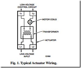
Actuators designated as line voltage have line-voltage inputs but commonly have a low-voltage control circuit since the motor is powered by low voltage. A transformer is used to supply power to the low voltage motor coils. It can be built into the actuator housing (Fig. 1) or supplied separately.
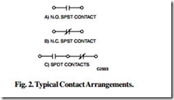
Contact arrangement: The electric switch configuration of a controller, relay, contactor, motor starter, limit switch, or other control device. Contacts which complete circuits when a relay is energized (pulled in) are called normally open (N.O.) or “in” contacts. Contacts which complete electric circuits when a relay is deenergized (dropped out) are called normally closed (N.C.) or “out” contacts. Many contact arrangements are available depending on the control device. Figure 2 illustrates three contact arrangements.
Control valve: A device used to control the flow of fluids such as steam or water.
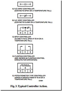
Controller: A temperature, humidity, or pressure actuated device used to provide two-position, floating, or proportioning control of an actuator or relay. It may contain a mercury switch, snap-acting contacts, or a potentiometer. Controllers can be two-wire or three- wire devices. Two-wire controllers are spst devices. The N.O. type (Fig. 3A) generally opens the circuit on a fall in the controlled variable and closes the circuit on a rise. The N.C. type (Fig. 3B) generally closes the circuit on a fall in the controlled variable and opens the circuit on a rise. Three-wire controllers are spdt, floating, or potentiometer devices. The spdt controllers (Fig. 3C) generally close R to B contacts and open R to W contacts on a fall in the controlled variable. The opposite occurs on a rise. The controllers in Figures 3A through 3C do not have a true N.O./N.C. contact arrangement but provide a switching action dependent on the condition of the controlled variable. Floating controllers (Fig. 3D) are spdt devices with a center-off position. Refer to SERIES 60 FLOATING CONTROL CIRCUITS for a discussion of floating control operation. Potentiometer controllers (Fig. 3E) move the wiper (R) toward B on a fall and toward W on a rise in the controlled variable. This action varies the resistance in both legs of the potentiometer and is used for proportional control.
Control Modes:
Modulating Control: When an actuator is energized, it moves the damper or valve a distance proportional to the sensed change in the controlled variable. For example, a Series 90 thermostat with a 10-degree throttling range moves the actuator 1/10 of the total travel for each degree change in temperature.
Two-Position Control: When an actuator is energized it moves the valve or damper to one of the extreme positions. The valve or damper position remains unchanged until conditions at the controller have moved through the entire range of the differential.
Floating Control: When an actuator is energized, it moves the damper or valve until the controller is satisfied. The actuator maintains that position until the controller senses a need to adjust the output of the valve or damper.
Damper: A device used to control the flow of air in a duct or through a wall louver.
Line voltage: A term which refers to the normal electric supply voltage. Line voltage can be used directly in some control circuits or can be connected to the primary side of a step down transformer to provide power for a low-voltage control circuit. Most line-voltage devices function at their rated voltage +10%/–15%. Line-voltage devices should be tested and listed by an appropriate approval agency.
Linkage: A device which connects an actuator to a damper or control valve. To open and close a damper, the typical linkage consists of an actuator crankarm, balljoints, pushrod, and damper crank arm. In a valve application, the linkage connects the actuator to the valve and translates the rotary output of the actuator to the linear action of the valve stem.
Low voltage: A term which applies to wiring or other electrical devices using 30 volts or less. Low-voltage control devices usually function on 24V ac +10%/–15%.
Relay: A device consisting of a solenoid coil which operates load-carrying switching contacts when the coil is energized. Relays can have single or multiple contacts.
Transformer: A device used to change voltage from one level to another. For control circuits this is usually line voltage to low voltage. Transformers can be used only on ac power.


