Switching Circuits
One-Way Switching Circuit
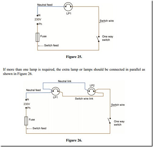
Figure 25 shows how a lamp is controlled by a simple one-way switch, providing on / off control of the lamp. The phase conductor is connected to the one-way switch, terminal C, through a suitably rated fuse or MCB, 6-10A. The neutral is connected directly to the lamp.
When the switch is closed the phase conductor is switched through to the lamp from terminal L1 and the 230 V supply is placed across the terminals of the lamp and so the lamp is illuminated.
When the switch is opened the phase conductor is interrupted and the lamp is extinguished. This occurs when the switch is in the “up” position.
Selective Switching Circuit
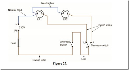
In Figure 27 a one-way switch is providing simple on / off control of the supply to a selector switch. This selector switch has two outputs. One of these outputs is used to feed lamp LP1, while the other feeds lamp LP2.
When the one-way switch is placed in the “on” position, either LP1 or LP2 will illuminate. When the selector switch is positioned as shown, LP1 will be “on” and LP2 will be “off”. If it is switched to the position shown by the dotted line, LP1 will be “off” and LP2 will be “on”.
In this way, one can select which lamp is “on” and which lamp is “off”. Both lamps cannot be “on” at the same time. This circuit was once used to provide two levels of lighting in certain circumstances. If LP1 were a 15 Watt lamp, it would provide a very low level of illumination in, say a child’s bedroom or a hospital ward. LP2 might, on the other hand, be a 100 Watt lamp and provide a high level of illumination.
Two-Way Switching Circuit
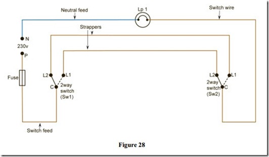
Figure 28 shows how a lamp can be controlled from two locations providing on / off control from either location. This circuit is used to control lamps in such places as stairways, corridors and rooms with two doorways.
The two-way switch has two outputs, sometimes labelled L1 and L2. The third terminal is referred to as the “Common” terminal and is marked “C” in some cases. This terminal is “common” to L1 & L2. In the “up” position the common is connected to L2 as shown, and therefore the lamp is “off”. If either switch is changed to the L1 position the lamp will be “on”. If both switches are changed to the L1 position the lamp will again be “off”. If the “strappers” are crossed over at either switch, the lamp will be “on” when both switches are in the “up” position. It is simply good practice to ensure that this does not occur. This means that it is possible to place all switches in the “up” position and be assured that all lamps are “off”. It also ensures safety when replacing faulty lamps or flex drops.
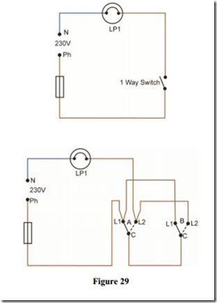
Figure 29 shows an alternative method of providing two-way switching. It is used to best advantage when a conversion from one-way to two-way control is required. Existing cables can be used without the unwanted extra connection at switch A, which would be required if the standard method was used.
Two-Way and Intermediate Switching Circuit
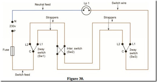
Figure 30 shows how a lamp can be controlled from three locations, providing on / off control from each of these locations. This circuit is used to control lamps in such places as stairways with more than one landing, long corridors and rooms with more than two doorways. If more than three switching locations are required it is simply necessary to add in extra intermediate type switches, at these locations.
The intermediate switch has four terminals. These terminals may be labelled in different ways, few of which are of any benefit to the installer. To complicate matters, there are two distinct types of intermediate switch. The more common type is shown in Figure 31. To consider how it functions we will number the terminals as follows:
In the “up” position terminals 1 and 2 are connected to terminals 3 and 4 respectively.
In the “down” position terminals 1 and 2 are connected to terminals 4 and 3 respectively. See Figure 32.
If we apply this information to the circuit above we can see that the lamp is “off”. By operating the intermediate switch, the lamp can be switched “on”. The two two-way switches operate as previously described. Other makes of intermediate switch may operate the opposite way round.
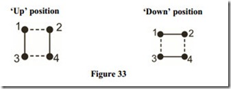
The other, less common type of intermediate switch operates as shown in Figure 33.
In the “up” position terminals 1 and 2 are connected to terminals 3 and 4 respectively.
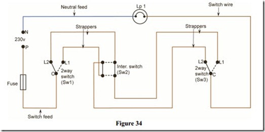
In the “down” position terminals 1 and 3 are connected to terminals 2 and 4 respectively. This type of switch will be connected as shown in Figure 34.
Again, if we apply the information regarding this type of intermediate switch, to the circuit shown in Figure 34, we can see that the lamp is “off”. By operating the intermediate switch, the lamp can be switched “on”. Alternate operating of the switches in any order will change the lamp condition i.e. “off” to “on” or “on” to “off”
It is obvious from Figure 34, that an intermediate switch has four terminals. It is important to remember that there are other types of switches, which have four terminals ( e.g. double pole switches ). The word “inter” or “intermediate” should be clearly marked on the back of an intermediate switch.
It is worth noting that a two-way switch or an intermediate switch can be used to complete the function of a one-way switch in a circuit. Also, an intermediate switch can be used instead of a two-way switch. This would only be done where the correct type of switch was not readily available.
